


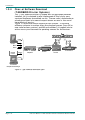

Introduction
Page 1-8 Instruction Manual: TT1260 Standard Definition Professional Receiver/Decoder
ST.TM.E10100.1
· Control Methods:
² Front Panel User Interface
² Asynchronous serial remote control
² Over-air remote control (TANDBERG Director system) (optional)
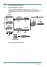
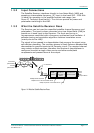
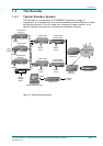
1.2.2 Inputs
ASI Inputs (Decoders)
Two BNC connectors support both byte-mode and single packet burst mode.
L-Band Inputs
Two F-type connectors connect the L-band output of a suitable LNB either
directly or via a suitable attenuator giving lightning and surge protection.
Remote Control
A 9-way D-type, male connector used to connect to a PC and can be
switched between the RS-232 and RS-485 input standards.
Frame Synchronisation
A BNC connector accepts a composite video input to which the video
output timing can be synchronised.
1.2.3 Outputs
Transport Stream Outputs
· Two BNC connectors output ASI transport streams with a maximum
data rate of 160 Mbit/s.
Video Outputs
· Two analogue composite video outputs carried on BNC connectors.
· Two digital video outputs carried on BNC connectors.
Audio Outputs
· Two 9-way D-type, female connectors decode two PES streams of
audio from the transport stream. The audio outputs simultaneous
analogue and digital. The digital mode can be changed via the user
interface.
Data Output
· RS-232 asynchronous low-speed data output carried on a 9-way,
D-type, female connector.
· RS-422 synchronous high-speed data output carried on a 9-way,
D-type, female connector.
Alarm Output
A 9-way D-type connector for alarm and failure monitoring is carried out
within the equipment. This produces a summary alarm signal that lights
the general front-panel ALARM LED.