


Installing the Equipment
Instruction Manual: TT1260 Standard Definition Professional Receiver/Decoder Page 2-13
ST.TM.E10100.1
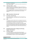
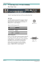
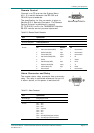
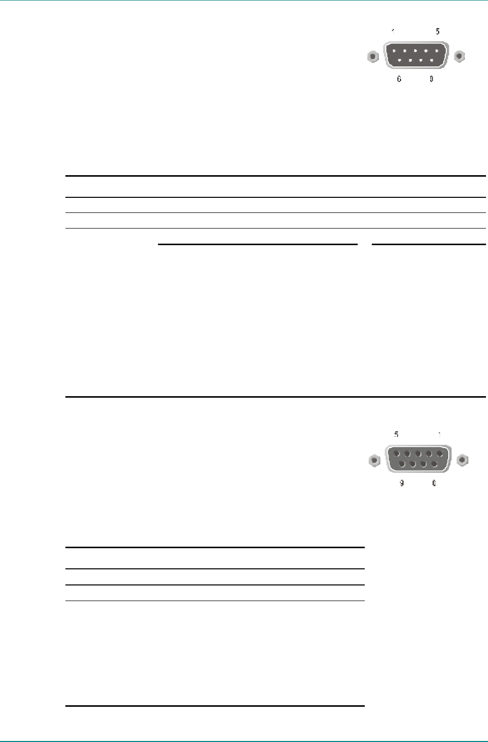
Remote Control
Connect to a PC and use the System Menu
#6.1.2 to switch between the RS-232 and
RS-485 input standards.
The specification for this connector is given in
Section B.5.4, Remote Connector. The Remote
Control Protocol is published in manual
ST.TS.E10100, and in the TANDBERG Television
RS-232 remote control protocol document.
RS232/RS485 REMOT
E
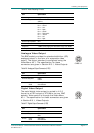
Table 2.10: Remote Control Connector
Item Specification
Connector type 9-way, D-type, Male
Connector designation RS232/RS485REMOTE
RS-232 RS-485
Pin-outs
Pin
1
2
3
4
5
6
7
8
9
Data Carrier Detected (DCD)
Receive Data (RxD)
Transmit Data (TxD)
Data Terminal Ready (DTR)
Ground
Data Set Ready (DSR)
Request to Send (RTS)
Clear to Send (CTS)
Not connected
Direction
Input
Input
output
output
—
input
output
input
—
Pin
1
2
3
4
5
6
7
8
9
Not connected
Not connected
Not connected
Rx
Ground
Not Tx
Tx
Not Rx
Not connected
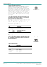
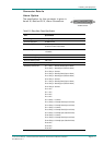
Alarm Connector and Relay
The master alarm relay connector has a summary
relay. The relay is activated whenever the unit is
in alarm status, or the power is switched off.
ALARM
Table 2.11: Alarm Connector
Item Specification
Connector type 9-way, D-type, Female
Connector designation ALARM
Pin-outs Pin 1 ¾ N/C
Pin 2 ¾ N/C
Pin 3 ¾ N/C
Pin 4 ¾ Common
Pin 5 ¾ N/C
Pin 6 ¾ N/C
Pin 7 ¾ N/C
Pin 8 ¾ Normally Closed (Open on Alarm)
Pin 9 ¾ Normally Open (Closed on Alarm)