


Installing the Equipment
Page 2-2 Instruction Manual: TT1260 Standard Definition Professional Receiver/Decoder
ST.TM.E10100.1
List of Figures
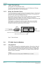
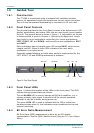
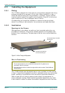
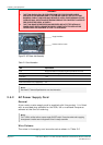
Figure 2.1: Air flow Through the Equipment...................................2-4
Figure 2.2: AC Power Inlet Assembly.............................................2-6
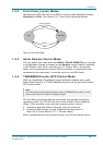
Figure 2.3: Location of the Technical Earth....................................2-8
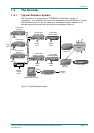
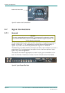
Figure 2.4: Typical Decoder Rear Panel ........................................2-8
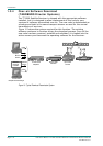
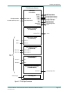
Figure 2.5: TT1260 Signal Connections.........................................2-9
Figure 2.6: Typical Decoder Rear Panel, with ASI Input and
Alarm Option Fitted .....................................................2-10
Figure 2.7: Alarm Relay Card Rear Panel....................................2-14
List of Tables
Table 2.1: Fuse Information........................................................... 2-6
Table 2.2: Supply Cord Wiring Colours ......................................... 2-7
Table 2.3: Non Standard Supply Cord Wire Colours..................... 2-7
Table 2.4: ASI Out Connector (2 Off) .......................................... 2-10
Table 2.5: Audio Decoding Pin-outs............................................ 2-11
Table 2.6: Analogue Output Connector (2 Off)............................ 2-11
Table 2.7: Digital Output Connector (2 Off)................................. 2-11
Table 2.8: Frame Sync Hi-Z Connector....................................... 2-12
Table 2.9: Ethernet Pin-outs........................................................ 2-12
Table 2.10: Remote Control Connector....................................... 2-13
Table 2.11: Alarm Connector....................................................... 2-13
Table 2.12: RS-232 Low-speed Data Connector......................... 2-14
Table 2.13: Relay Alarm Output Specification............................. 2-15