


Installing the Equipment
Instruction Manual: TT1260 Standard Definition Professional Receiver/Decoder Page 2-15
ST.TM.E10100.1
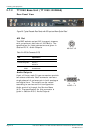
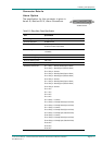
Connector Details
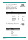
Alarm Option
The specification for this connector is given in
Annex B, Section B.5.5, Alarm Connectors.
25
1
A
LARM OPTION
Table 2.13: Relay Alarm Output Specification
Item Specification
Connector type: 25-way, D-type, Female
Connector designation: ALARM OPTION
Contact Configuration: SPDT (Change-over)
All volt-free contacts, fully isolated.
Contact Rating: 1A at 24Vdc
1A at 50Vac
Maximum Switching Current: 1A
Maximum Switching Voltage: 50Vdc/30Vac
Maximum Switching Power: 24W / 60VA
Minimum Switching Load: 0.1mA, 100mVdc
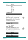
Alarm Relay Card Pin-outs Pin 1 - Relay 1 – Normally Closed (Open on Alarm)
Pin 2 - Relay 1 – Normally Open (Closed on Alarm)
Pin 3 - Relay 2 – Common
Pin 4 - Relay 3 – Normally Closed (Open on Alarm)
Pin 5 - Relay 3 – Normally Open (Closed on Alarm)
Pin 6 - Relay 4 – Common
Pin 7 - Relay 5 – Normally Closed (Open on Alarm)
Pin 8 - Relay 5 – Normally Open (Closed on Alarm)
Pin 9 - Relay 6 – Common
Pin 10 - N/C
Pin 11 - N/C
Pin 12 - N/C
Pin 13 - N/C
Pin 14 - Relay 1 – Common
Pin 15 - Relay 2 – Normally Closed (Open on Alarm)
Pin 16 - Relay 2 – Normally Closed (Open on Alarm)
Pin 17 - Relay 3 – Common
Pin 18 - Relay 4 – Normally Closed (Open on Alarm)
Pin 19 - Relay 4 – Normally Open (Closed on Alarm)
Pin 20 - Relay 5 – Common
Pin 21 - Relay 6 – Normally Closed (Open on Alarm)
Pin 22 - Relay 6 – Normally Open (Closed on Alarm)
Pin 23 - N/C
Pin 24 - N/C
Pin 25 - N/C