


Options
Instruction Manual: TT1260 Standard Definition Professional Receiver/Decoder Page 5-5
ST.TM.E10100.1
5.3.3 Connector Details
L-band Inputs
Connect the L-band output of a suitable LNB to
the F-type connector either directly or via a
suitable attenuator giving adequate consideration
to lightning and surge protection – refer to
Section 2.3.4, Outdoor Antenna. The active input
is chosen using the Input Status Menu (#2).
In most cases an attenuator will not be required.
The following list summarises the circumstances
when one should be used.
When the desired input level is greater than the
specified maximum permissible
(-25 dBm).
When the downlead is a short length of low-loss
cable and the LNB in use has a poor return loss
(7 dB min).
When the Receiver is receiving one of many
carriers in a multi-carrier FDM system and the
level of the wanted signal is close to the specified
maximum permissible.
The specification for this connector is given in
Section B.4.1, QPSK Satellite Receivers.
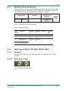
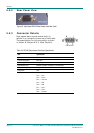
Table 5.3: QPSK Satellite Receiver (L-band) Connector (2 Off)
Input Specification
Connector type F-type, Female
Connector designation QPSK IN 1
QPSK IN 2
Pin: Centre
Shield
RF Input
Ground/Chassis
LNB Supply Refer to Caution box below
Impedance 75 W
CAUTIONS...
1. The Receiver provides dc power (refer to Chapter 3, Operating the Equipment Locally) via the active
L-band input connector to drive an LNB (Low Noise Block Down-Converter). Do not connect
equipment other than an LNB to this connector. Failure to do this may result in damage to the
external equipment.
2. The F-type connector is not suitable for repeated connection and disconnection. When intended for
use in this way, fit a sacrificial connector and connect to it.
QPSK IN 1/2