


45
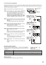
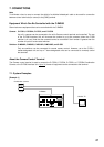
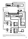
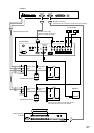
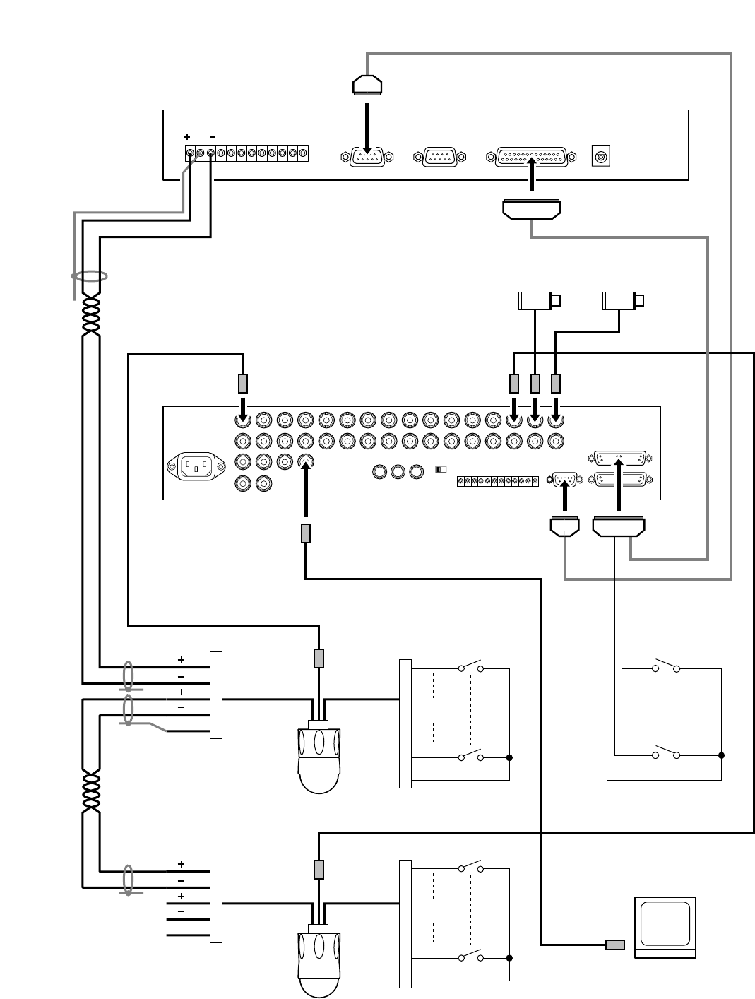
Camera input/output
Monitor output
Alarm I/O
RS-232C
IN IN
2
12
12
34567891011 12 13 14 15 16
Multi-switcher
Monitor TV
Fixed camera
*
*
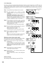
C-RM500
Sensor
1
4
6
9
5, 10
Sensor
1
4
6
9
5, 10
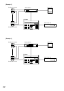
A
B
A
B
Combination camera
Combination camera
1
2
3
4
5
1
2
3
4
5
Camera control
cable
Alarm input
cable
Camera control
cable
Alarm input
cable
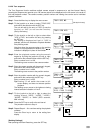
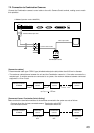
Shielded twisted-pair cable
GND
Camera control terminal
Alarm output terminal
Switcher control terminal
RS-232C
Sensor
AB
RS-232C reverse cable
Female D-sub 9-pin connector to Female D-sub 9-pin connector
The use of each camera's alarm input permits
connection of 8 sensors for each camera.
Corresponding to
the fixed camera A
Corresponding to
the fixed camera B
* Connect this cable only when "2. LEVEL" is selected in the unit's "Alarm signal" setting. (Refer to p. 35.)
Connect the C-RM500's alarm output corresponding to the Combination Camera address to the Multi-
Switcher's alarm input, while leaving other output terminals not corresponding to any Camera address
unconnected.