


6
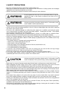
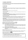
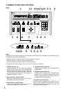
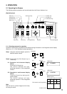
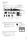
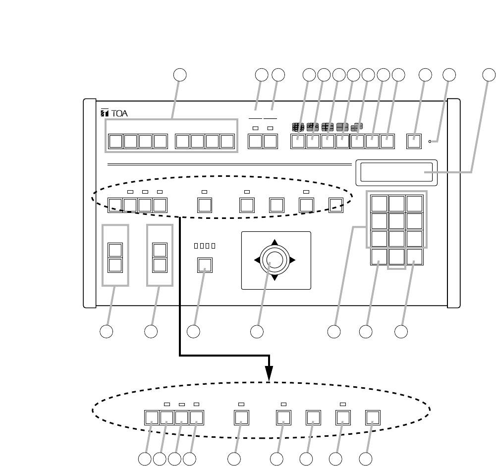
4. NOMENCLATURE AND FUNCTIONS
[Top]
A B C D
WIPER
ZOOM
TELE
WIDE
FOCUS
FAR
NEAR
LENS SPEED
UP
DOWN
RIGHTLEFT
LOW HIGH
DEF AUX AUTO
E F G H
SELECT
MENU
GROUP
CH
SEQUENCE
FUNCTION
ALARM
RESET HOLD
AF POSITION CONTROLFREEZE FULL
WIPER DEF AUX AUTO AF POSITION CONTROLFREEZE FULL
REMOTE CONTROLLER C-RM500
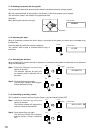
1 2 3
4 5 6
7 8 9
C
0
SET
1 2 3 4 5 6 7 8 9 10
21
22 23
24
25
26
27 28 29
11 12 13
14 15 16
18 19
17
20
Notes
Depending on the system configuration, the operation of some keys may be disabled. The corresponding keys
are marked with the following indications.
*
1
Does not function in systems using only with Combination cameras.
*
2
Does not function in systems using the Smart Switcher.
*
3
Functions only when connected to the Combination camera.
*
4
Connect the DC power supply of 12 V/over 150 mA to either input terminal.
1. Function keys [A – H]
A single depression of one of these keys displays
the full-screen image of the key's corresponding
camera number and position number. Each key
can also be set to activate automatic operations
(panning, tracing, and sequential switching) of the
selected Combination camera.
2. Alarm reset key / Alarm indicator
Resets the system's Alarm mode. The indicator
light flashes during Alarm operation.
3. Alarm hold key / Hold indicator
Places activated Alarm inputs on hold. The
indicator light flashes during Alarm Hold.
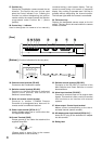
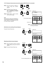
4. 16-segment split-screen key *
1
, *
2
Displays camera images in the 16-segment split-
screen format.
5. 10-segment split-screen key *
1
, *
2
Displays camera images in the 10-segment split-
screen format. Subsequent depressions of this
key can toggle between two separate groups of
10-segment split-screen displays.
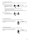
6. 9-segment split-screen key *
1
, *
2
Displays camera images in the 9-segment split-
screen format. Subsequent depressions of this key
can toggle between two separate groups of 9-
segment split-screen displays.