


• The explanations in this manual assume that the C-RM500 Remote Controller is connected to a
C-MS160D/S or C-MS90D/S Multi-Switcher and the C-SS8 Smart Switcher.
• Camera number: Refers to the camera input terminal number connected to the switcher.
• Position number: Combination camera orientation can be programmed for No. 1 – 255.
5
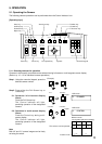
2. GENERAL DESCRIPTION
The TOA C-RM500 Remote Controller is used to remotely control TOA's Combination cameras over
communication lines (RS-485). It can remotely control video image switching and cameras in combination with
TOA's Multi-Switcher or Smart Switcher.
3. FUNCTIONS
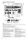
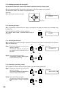
• Display Selection
The following screen formats can be selected for display of camera images connected to the Multi-Switcher:
full screen, 4-segment, sequential 4-segment, 9-segment, 10-segment or 16-segment split-screen and
sequential full-screen.
• Manual Operation
Controls the Combination camera's zoom, focus, pan and tilt functions.
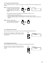
• Camera Position Selection
Controls the Combination camera's orientation, and displays the camera image on the monitor in the
selected orientation.
• Function Key Programming
Camera numbers or camera number/position combinations can be programmed into the function keys (A –
H). Pressing the function key displays the camera image on the full screen. If position numbers have been
set, images of the selected camera orientation can be displayed.
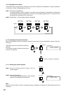
• Abbreviated Number Display
Permits camera numbers or camera number/position combinations to be programmed for numbers 1 – 512.
Entering the programmed number followed by the SET key displays the corresponding camera number on
the full screen, and the image of selected camera orientation if the position number has been set.
•Alarm Function
Controls the display in synchronization with alarm signals received from a camera. When an alarm signal is
detected, the image of the corresponding camera takes display precedence. The C-RM500 Controller also
features an Alarm Hold function that temporarily disables channel (camera number) switching in response to
an alarm signal. This prevents the display from being forcibly switched to an alerted camera during close
inspection (when the Multi-Switcher is connected).
Equipment Which Can Be Controlled with the C-RM500
Shown below are equipment that can be controlled with the C-RM500.
Camera: C-CC501, C-CC504, C-CC551, and C-CC554
Up to 31 cameras can be connected to the unit's Camera control terminal and controlled. The use
of the C-IF500 Interface Unit will increase the number to up to 64 cameras (when the C-SS8
switcher is in use). Note that the cameras cannot be controlled if their number is greater than the
number of inputs of a connected switcher.
Switcher: C-MS90D, C-MS90S, C-MS160D, C-MS160S, and C-SS8
Only one switcher can be connected for remote camera control. However, as to the C-SS8, 1
master-designated unit and up to 7 slave-designated units can be connected to remotely control
the cameras.
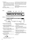
About the Camera Control Terminal
The Camera control terminal is used to connect the C-CC501, C-CC504, C-CC551, or C-CC554 Combination
Camera or the C-IF500 Interface Unit. Up to 31 pieces of equipment can be connected to the terminal.
About the Descriptions in This Manual