


8
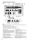
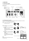
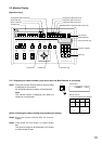
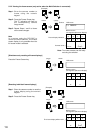
27. Position key
Orients the Combination camera toward the set
direction. The Position key can only be used
when the Control indicator is on. Pressing the
Position key without designating the position
number orients the camera toward the direction
programmed under Position No. 1 (Home
position).
28. Control key *
2
/ Indicator
Used to designate the camera to be manually
controlled during a multi-screen display. This key
cannot be used during a full-screen or sequential
display. Also, nothing is operated even if this key is
pressed without designating the channel number.
The indicator lights when the camera is controllable.
29. Full-screen key
Displays the designated camera output on the full
screen. This key cannot be used unless the camera
number is entered.
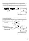
SWITCHER
SWITCHER REMOTECAMERA
GND GND GND GND GND
DC IN
12V
REMOTE CONTROLLER
model C-RM500 120
TOA Corporation
MADE IN JAPAN
ALARM IN ALARM OUT
DC IN 12V
30
31
32
33
34
35
36
37
38
12V 150mA Class2
39
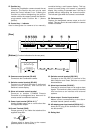
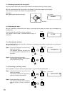
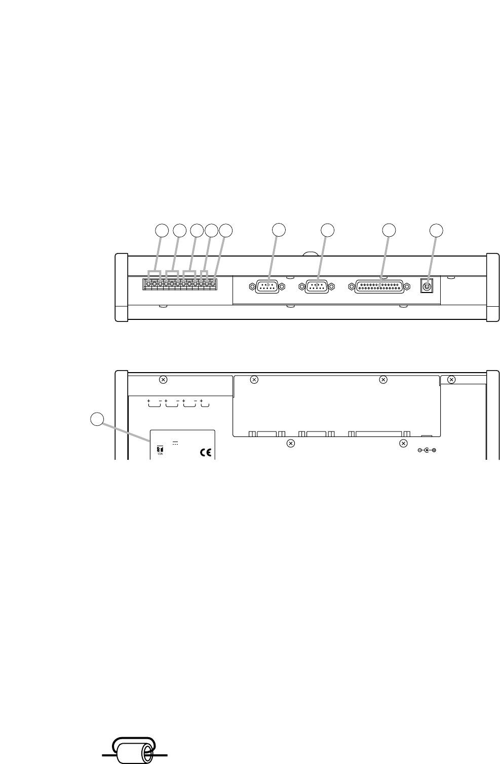
[Rear]
[Bottom]
(Function indications for the rear parts)
30. Camera control terminal (RS-485)
Connects to the Combination camera.
31. Switcher control terminal (RS-485)
Connects to the Multi-Switcher's dedicated
remote control terminal, and controls the
Switcher's screen display.
32. Slave unit remote control terminal
Connects to another C-RM500 Remote
Controller to be designated as a slave unit for
remote control from different locations.
33. Power input terminal [DC IN 12 V] *
4
Used to supply power from a source other than
the supplied AC adapter.
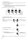
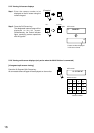
34.Ground Terminal [GND]
Please ground by the cable that attached the
supplied clamp filter.
(Please attach a clamp filter to the nearest
possible position of this controller.)
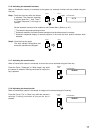
35. Switcher control terminal (RS-232C)
Connects to the RS-232C I/O terminal of the
Multi-Switcher and Smart Switcher to control
these switchers.
36. Alarm input terminal (RS-232C)
Connects to an alarm input unit to receive alarm
signals. This terminal is also a serial I/O terminal
that functions as an interface with external
systems.
37. Alarm output / Control input terminal
Makes contact corresponding to the alarm-
activated channel (camera number).
38. AC adapter power input terminal [DC IN 12 V] *
4
Insert the DC plug of the dedicated AC adapter
into this terminal.
39. Rating label
1turn
GND
GND
Te rminal
clamp filter