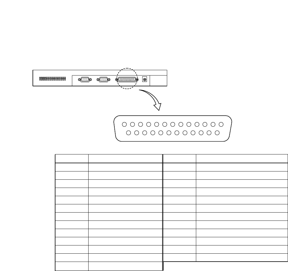
49
Alarm output / control input terminal
13
25
14
1
C-RM500
Pin No. Function Pin No. Function
1Ground 14 Alarm Output 10
2Alarm Output 1 15 Alarm Output 11
3Alarm Output 2 16 Alarm Output 12
4Alarm Output 3 17 Ground
5Ground 18 Alarm Output 13
6Alarm Output 4 19 Alarm Output 14
7Alarm Output 5 20 Alarm Output 15
8Alarm Output 6 21 Alarm Output 16
9Ground 22 Alarm Output
10 Alarm Output 7 23 Alarm Input
11 Alarm Output 8 24 Home Position Selection Input
12 Alarm Output 9 25 Auxiliary Input
13 Ground
7.6. Alarm Output/Control Input Terminal Connections
7.6.1. Pin functions
Shown below are the numbers and names of the Alarm I/O terminal pins.
[Alarm Output Terminal] (Pin No. 1 – 16)
The terminal of the number corresponding to the alarm-activated camera number shorts with the ground
terminal. Alarm output terminals 1 – 16 are the NPN open collector output.
Operating current: Maximum 20 V, 20 mA
[Alarm Output Terminal] (Pin No. 22)
This terminal is shorted with the ground terminal even when only one of the alarm input terminals receives an
alarm signal. The alarm output terminal is the NPN open collector output.
Operating current: Maximum 20 V, 20 mA
[Alarm Input Terminal] (Pin No. 23)
Shorting this terminal with the ground terminal when "OTHER16," "OTHER16-64" or "OTHER" has been
selected in the "SWITCHER" setting will sound a buzzer and cause the Alarm Reset indicator to flash while it
is shorted. (Refer to p. 25 "Switchers.")
Open voltage: 5 V DC, short-circuit current: Maximum 5 mA
[Home Position Selection Input Terminal] (Pin No. 24)
When Auto-Return is performed while this terminal is being shorted to the ground terminal, the camera's
operation follows the setting made for "2" in the "Home position" setting. (Refer to p. 28 "Home position.")
Open voltage: 5 V DC, short-circuit current: Maximum 5 mA
[Auxiliary Input] (Pin No. 25)
Leave this input unconnected.
Open voltage: 5 V DC, short-circuit current: Maximum 5 mA


