


144 Firmware Upgrades Color Active Touch Panels
ODD
EVE
199
CORP.
50-0940
AXT-
P
P
G
P
J
JP
JP
JP
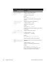
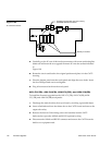
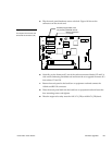
Memory IC sockets
Erasable programmable read only memory
(EPROM) sockets for firmware
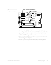
5. Carefully pry the ICs out of their socket connectors with a non-conducting flat-
blade tool and insert the two upgrade firmware ICs into the sockets indicated
in
Figure 198.
6. Rotate the circuit card back to the original position and place it in the CATP
housing.
7. Place the bottom panel onto the touch panel and align the screw holes. Insert
the four Phillips-head screws and tighten.
8. Plug all connectors back into the touch panel.
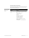
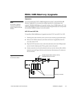
AXU-CV(/PB), AXU-CA(PB), AXM-CV(/PB), and AXM-CA(PB)
To install the firmware upgrade into the AXU-CV(/PB), AXU-CA(PB), AXM-
CV(/PB), and AXM-CA(PB) touch panels:
1. Discharge the static electricity from your body by touching a grounded object.
2. Insert a flat-blade tool into the release slot on the CATP’s bezel and remove the
engraved overlay.
3. Remove the four #6-32 mounting screws and carefully lean the CATP
backward to expose the AXlink and RS-232 (optional) wiring.
4. Disconnect the AXlink and RS-232 connector and remove the CATP from the
back box or equipment rack.
Figure 198
IC connector sockets