


Color Active-Matrix LCD Touch Panels Installing Touch Panels 13
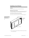
4. Insert the AXM-CV(/PB) or AXM-CA(/PB) into the rack. Line up the top left
and right screw holes and start the #6-32 screws. Then, start the bottom left
and right screws. Tighten all the screws after you start all the screws.
5. Connect the AXlink wiring to the AMX Central Controller and RS-232 wiring
to the external RS-232 device. The AXM-CV(/PB) or AXM-CA(/PB) will beep
when you apply power.
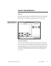
Wiring the Touch Panels
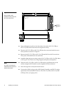
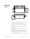
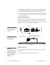
The CATPs use a four-pin AXlink connector for power and data. Figure 11 shows
the rear panel AXlink connector on the TiltScreen color active and color video
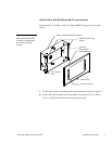
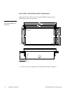
touch panels. Figure 12 shows the rear panel AXlink connector on the UniMount
and rack-mount color active and color video touch panels.
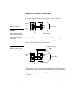
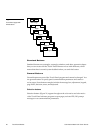
Rear view
Video models only
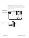
Top view
4-pin (male) AXlink connector
RS-232 (male) connector
RCA Video connector - video
models only
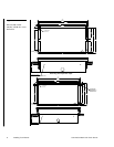
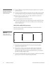
Preparing captive wires
You will need a wire stripper and flat-blade screwdriver to prepare and connect
the captive wires.
1. Strip 0.25 inch (6.35 mm) of wire insulation off all wires.
Figure 11
TiltScreen Color and Video
Touch Panel connectors
(rear view)
Figure 12
Rack-Mount CATP
connectors (top view)
Caution
Do not connect power to the
Touch Panel until the wiring is
complete. If you are using a
12 VDC power supply, apply
power to the Touch Panel
only after installation is
complete.