


12 Installing Touch Panels Color Active-Matrix LCD Touch Panels
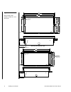
8. Fasten the BB-TP1 to the plasterboard using the expansion screws supplied
with the enclosure.
9. Connect the AXlink and RS-232 wiring to the AXU-CV(/PB) or AXU-CA(/PB)
circuit card. Refer to Wiring the Touch Panel for complete wiring information.
10. Fasten the AXU-CV(/PB) or AXU-CA(/PB) to the BB-TP1 with the #6-32
screws supplied with the enclosure.
11. Insert the engraved overlay back into the bezel.
12. Connect the AXlink wiring to the AMX Central Controller and RS-232 wiring
to the external RS-232 device. The AXU-CV(/PB) or AXU-CA(/PB) will beep
when you apply power.
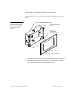
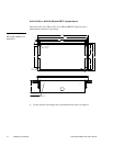
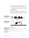
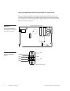
AXM-CV(/PB) or AXM-CA(/PB) (rack-mount)
Mount the AXM-CA(/PB) or AXM-CA(/PB) (Figure 10) rack-mount into an
electronic equipment rack.
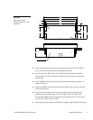
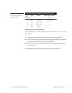
1. Thread the incoming AXlink and RS-232 (optional) wiring through the
opening in the equipment rack.
2. Disconnect the AXlink connector from the AMX Central Controller that
supplies power and data to the AXM-CV(/PB) or AXM-CA(/PB). Then,
disconnect the DB-9 connector from the external RS-232 device connected to
the AXU-CV(/PB) or AXM-CA(/PB).
3. Connect the AXlink and RS-232 wiring to the AXM-CV(/PB) circuit card. Refer
to Wiring the Touch Panel for complete wiring information.
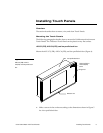
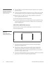
Note
The CATP must always be
installed with the release slot
located at the bottom.
Figure 10
AXM-CV(/PB) or AXM-
CA(/PB) Rack-Mount CATP