


Color Active-Matrix LCD Touch Panels Installing Touch Panels 11
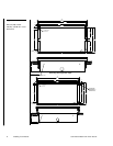
.125 [3.2 MM] MAX
CUTOUT
TWO .170 [4.3 MM] DIA HOLES PROVIDED ON
2.94
1.70
1.70
.125
4.25
7.10
7.46
7.80
.35
.170
.52
3.22
(FRAME)
(FRAME)
[74.7 MM]
[8.9 MM]
[180.3 MM]
8.187
4.50
2. Insert a flat head screwdriver into the release slot on the AXU-CV(/PB)’s or
AXU-CA(/PB)’s bezel and remove the engraved overlay.
3. Lay the AXU-CV(/PB) or AXU-CA(/PB) facedown onto a soft cloth and
remove the four screws from the low-profile back box. Remove the back box
and discard.
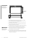
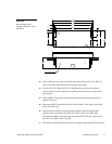
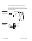
4. Place the BB-TP1 into the cutout and mark the threaded insert positions as
shown in Figure 9.
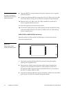
5. Remove the BB-TP1 and drill four #6-32 insert holes. Then, place a threaded
insert into each hole.
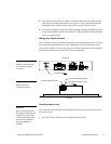
6. Disconnect the AXlink connector from the AMX Central Controller that
supplies power and data to the AXU-CV(/PB) or AXU-CA(/PB). Then,
disconnect the DB-9 connector from the external RS-232 device connected to
the AXU-CV(/PB) or AXU-CA(/PB).
7. Thread the incoming AXlink and RS-232 wiring through the BB-TP1 knockout.
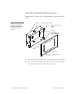
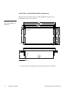
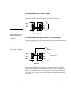
Figure 9
AXU-CV(/PB) or AXU-
CA(/PB), and BB-TP1 cutout
dimensions