


Color Active Touch Panels Firmware Upgrades 145
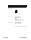
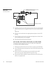
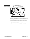
5. Flip the touch panel facedown onto a soft cloth. Figure 199 shows the
connectors on the circuit card.
EVEN
ODD
8
1
1
5
J1
CORP.
1996
50-0941 REV.A
AXU-CV
5
1
JP1
JP2
JP3
JP6
JP5
U3
U6
U4
U5
U21
U20
U22
U1
Y3
U11
U7
U9
U8
U10
P4
P3
U19
P5
SPKR1
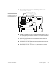
Memory expansion
IC sockets
Erasable programmable read
only memory (EPROM) sockets
6. Carefully pry the firmware ICs out of the socket connectors labeled U5 and U6
with a non-conducting flat-blade tool and insert the two upgrade firmware ICs
into sockets U5 and U6.
7. Return the touch panel to the back box or equipment rack and connect the
AXlink and RS-232 connector.
8. Place the touch panel back into the back box or equipment rack and insert the
four mounting screws and tighten.
9. Place the engraved overlay onto the AXU-CV(/PB) or AXM-CV(/PB) bezel.
Figure 199
Touch panel circuit card, and
32-socket IC connector (U4)