


Color Active-Matrix LCD Touch Panels Installing Touch Panels 9
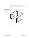
3. Lay the AXU-CV(/PB) or AXU-CA(/PB) facedown onto a soft cloth and
remove the four screws from the low-profile back box. Remove the back box
and discard.
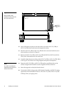
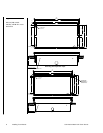
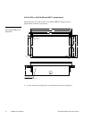
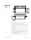
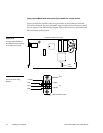
4. Place the BB-TP1 into the cutout and mark the threaded insert positions as
shown in Figure 7.
5. Remove the BB-TP1 and drill eight holes as shown in Figure 6. Then, place #6-
32 threaded inserts into the four holes marked ‘B’ in the cutout dimensions
illustration.
6. Disconnect the AXlink connector from the control system that supplies power
and data to the AXU-CV(/PB) or AXU-CA(/PB). Then, disconnect the DB-9
connector from the external RS-232 device connected to the AXU-CV(/PB) or
AXU-CA(/PB).
7. Remove one or more knockouts to accommodate the wiring as required.
8. Thread the incoming AXlink and RS-232 wiring through the BB-TP1 knockout.
9. Fasten the BB-TP1 to the solid surface with the mounting screws supplied with
the enclosure.
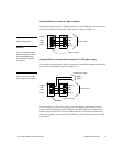
10. Connect the AXlink and RS-232 wiring to the AXU-CV(/PB) or AXU-CA(/PB)
circuit card. Refer to Wiring the Touch Panel for complete wiring information.
11. Fasten the AXU-CV(/PB) or AXU-CA(/PB) to the BB-TP1 with the #6-32
screws provided with the enclosure.
12. Insert the engraved overlay back into the bezel.
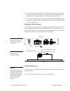
13. Connect the AXlink wiring to the AMX control system and RS-232 wiring to
the external RS-232 device. The AXU-CV(/PB) or AXU-CA(/PB) will beep
when you apply power.
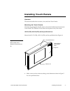
Note
The CATP must always be
installed with the release slot
located at the bottom.
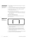
Note
The BB-TP1 can also be
mounted to wood or metal
studs using the pre-drilled
stud mounting holes.