


2
525 Programmable Motion Controller
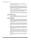
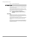
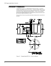
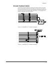
Figure 1 External Disconnect Example
AC Input Line
The AC line voltage of the input power must be within the specified range and free
of voltage transients that exceed this range. If this is not the case, additional AC
line conditioning may be required.
The AC input lines are connected to the 3-position terminal strip (L1, L2, GND)
located on the bottom plate of the 525 PMC. Power to the 525 PMC and the external
drive must be applied at the same time. To ensure proper operation after removing
power, wait a minimum of 10 seconds before re-applying power.
NOTE: The application of AC power to the 525 PMC must be
simultaneous with application of AC power to the controlled
external drive.
Grounding
The 525 PMC is internally grounded. The primary function of proper chassis
grounding is to ensure that the earth ground is connected to the AC ground input
of the chassis. Ground connections must be made from the chassis ground terminal
on each piece of equipment to a unique single point ground.
Connections should use the same gauge wire as the power input wire to the device
and not be shared with any other equipment. The motor cable should contain a
motor frame ground wire of at least the same gauge as the armature power
conductors.
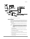
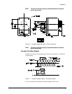
All electrical cabinets and machine elements must be ground bonded together. 2
shows a typical grounding arrangement. To ensure proper grounding techniques,
please observe the recommendation of the IEEE Ground Book, ANSI Standards,
and the National Electrical Code.