


26
525 Programmable Motion Controller
In 525's, the signal terminator capacitance is approximately 1000pf and a typical
cable capacitance runs about 30pf/ft. Therefore, the cable length should be limited
to 50 feet. Longer serial interface cables are not recommended.
In multi-drop configurations, the ground reference (earth ground) for each
communicating device must be at the same potential. The further apart the
communicating devices, the more difficult this is to achieve. Therefore, it is a good
idea to keep the multi-drop loop as short as possible. This condition is not as critical
if all of the communicating devices are optically isolated.
It is very important that the serial cables are not altered in the field. It is also
important to follow any recommendations given in the product manuals on how to
connect or terminate these cables.
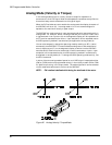
NOTE: As a general rule, the minimum cable bend radius is ten times
the cable outer diameter.
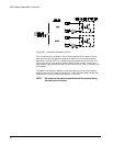
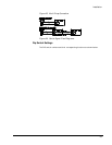
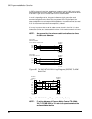
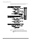
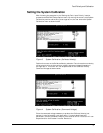
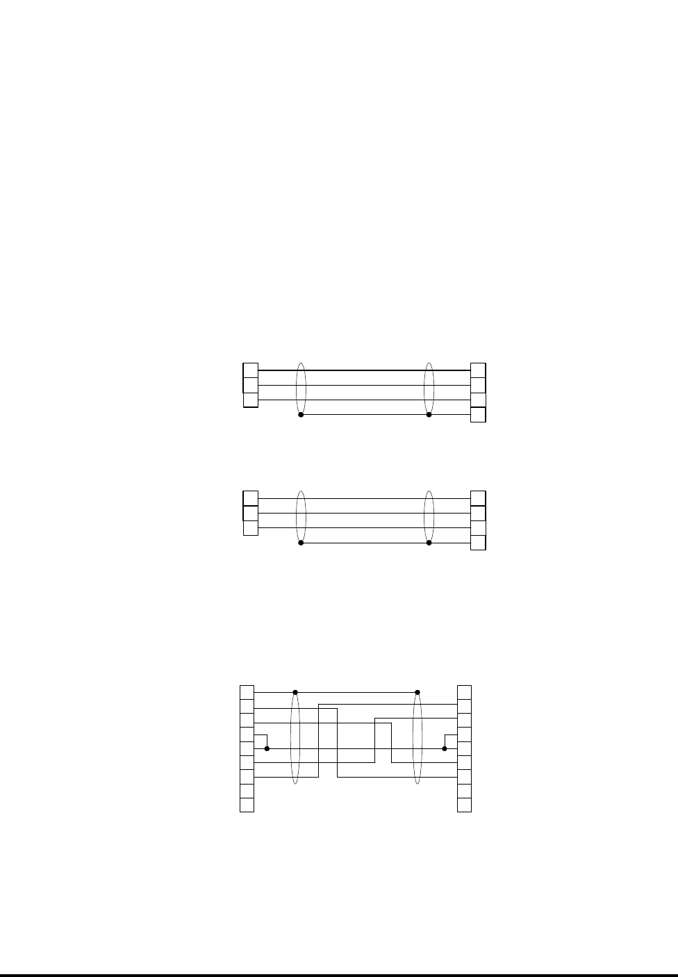
Figure 28 TIX-XXX & TIA-XXX Wiring Diagrams (525 PMC To IBM
Serial Port)
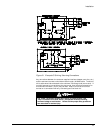
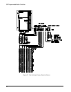
Figure 29 DD-XXX Wiring Diagram ( Multi-Drop Cable)
NOTE: For wiring diagrams of Emerson Motion Control T-60 (NMA-
XXX), T-61 (NMB-XXX) or T-21 refer to the operators manual that
accompanied that device.
FX DRIVE
SERIAL A
5
2
1
3 RX
SHLD
GND
9 PIN MALE
"D" TYPE
TIX-25 CABLE
COMPUTER/TERMINAL
TYPICAL IBM 25F PIN RS232 STYLE
7
2
3REC
GND
XMIT REC
SHIELD
FX DRIVE
SERIAL A
5
2
1
3 RX
SHLD
GND
9 PIN MALE
"D" TYPE
TIX-25 CABLE
COMPUTER/TERMINAL
TYPICAL IBM 9F PIN STYLE
5
3
2REC
GND
XMIT REC
SHIELD
FX DRIVE 2
SERIAL A
3
9
8
7
6
5
1
4
2 RX
N/C
TXM
RXM
GND
MEN
TX
N/C
9 PIN MALE
"D" TYPE
FX DRIVE 1
SERIAL B
3
9
8
7
6
5
1
4
2RX
N/C
TXM
RXM
GND
MEN
TX
N/C
9 PIN MALE
"D" TYPE
SHLD