


10
525 Programmable Motion Controller
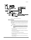
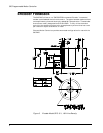
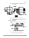
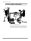
External Drive Connections To The 525 PMC
The 525 PMC has two keyed, detachable terminal blocks on the bottom of the unit
for connecting the external drive and encoder. The terminal blocks are divided into
two sections of 13 (1-13 & 14-26). Connections should be made using wire no larger
than 18ga. The following is a breakdown of the signals available at the terminal
blocks.
Connector Pin#Signal Description
1 Encoder signal input A
2 Encoder signal input A not
3 Encoder signal input B
4 Encoder signal input B not
5 Encoder signal input M
6 Encoder signal input M not
7 Encoder +5VDC Supply
8 Encoder Shield & Command Shield
9 Encoder Ground
10 Command (+)
11 Command (-)
12 Feedback current (+)
13 Feedback current (-)
14 Input 1 (+)
15 Input 1 (-)
16 Input 2 (+)
17 Input 2 (-)
18 Reserved for future use
19 Reserved for future use
20 Shield
21 Drive enable NORMALLY ON (-) EMITTER
22 Drive enable NORMALLY OFF (-) EMITTER
23 Drive enable (+) Common Collector (dirve enable only)
24 Drive reset NORMALLY ON (-) EMITTER
25 Drive reset NORMALLY OFF (-) EMITTER
26 Drive reset (+) Common Collector (drive reset only)
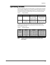
Signal Discriptions
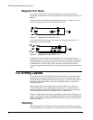
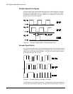
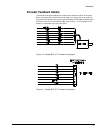
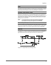
Encoder input signals
The encoder input signals - A, A not, B, B not, M, M not are directly connected to
the motor encoder. The signals should have a minimum 2.5 V and a maximum 5.0
VDC peak to peak voltage with a 2.5 VDC reference. Sine wave encoders are
recommended due to their inherent noise immunity. Square wave encoders can also
be used if care in cable selection is taken.
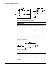
Encoder +5VDC supply
+5VDC and ground is provided to power the encoder. Maximum current output is
150 ma. If the encoder to be used exceeds this limit an external power supply will
have to be provided and grounded to the encoder ground on the terminal block.