


27
Installation
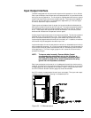
Input Output Interface
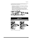
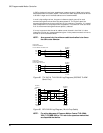
The 525 is equipped with 8 inputs and 4 outputs which operate on +10 to +30 vdc.
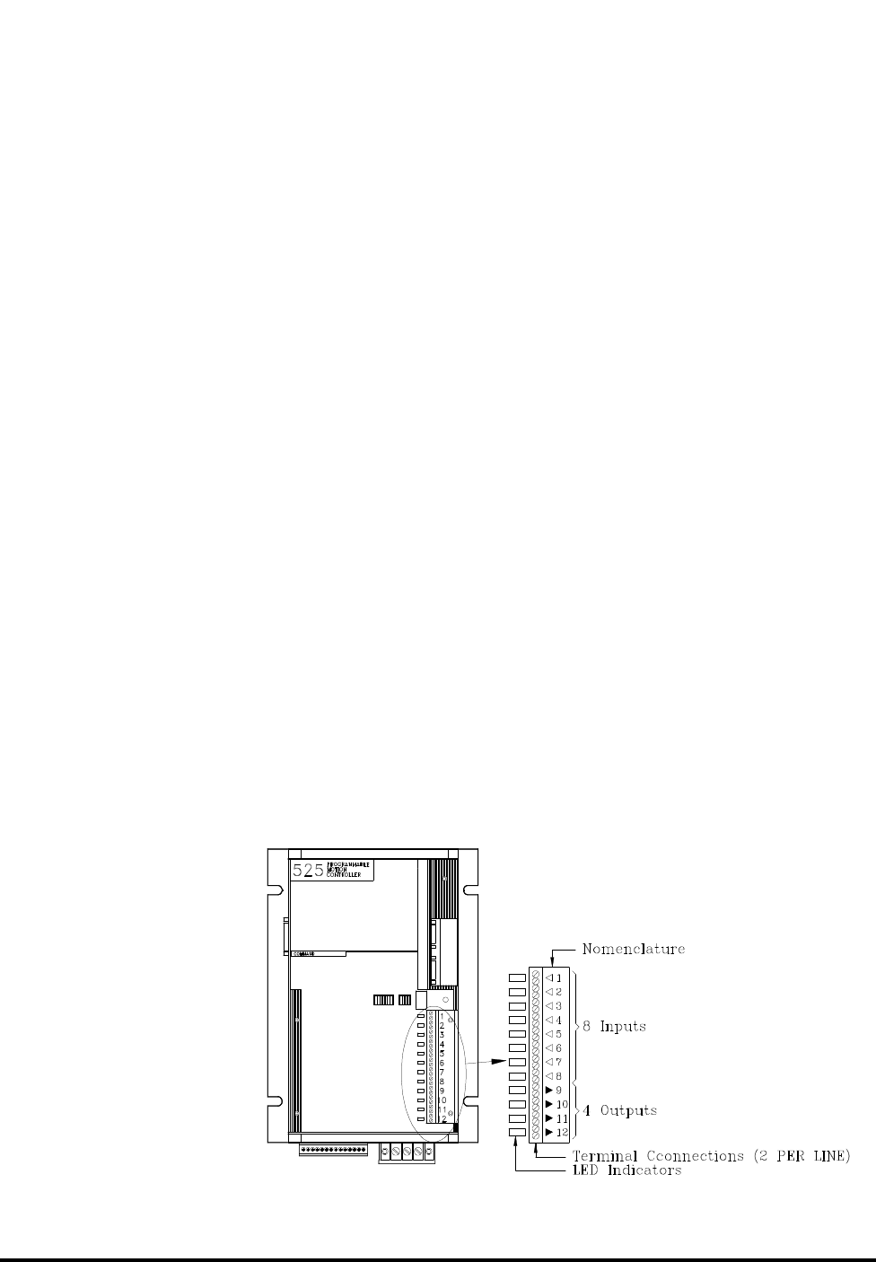
Each input and output has 2 screw terminals associated with it to provide for either
sinking or sourcing operation. The first 8 pairs of designated terminals are inputs
and the last 4 pairs of terminals are outputs (see 30). The outputs are capable of
sinking or sourcing 200 mA. It is the operators responsibility to limit the output
current to less than or equal to 200 mA.
These inputs and outputs allow for proper timing and coordination between the
525's motion and other machine control functions. The inputs and outputs typically
are connected to the machine's programmable logic controller (PLC) or external
drive. These inputs and outputs can also be connected to limit switches, and/or
switches and indicators on an operator's control panel.
A wide range of input/output control functions are provided. The functions used are
assigned to any of the input/output lines. This is accomplished through either
serial interface commands or by using the PCX software provided with the 525.
Inputs may be programmed as normally off or normally on. In addition, more than
one function may be assigned to the same input line.
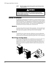
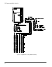
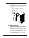
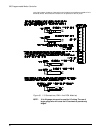
Inputs and outputs for control and status are wired to a detachable terminal strip
which makes servicing easy. All I/O wiring must be done with 18 to 24 gauge wire
and must be industrial grade insulated wire that will withstand the environment
of the application. The use of larger gauge wire will cause the I/O terminals to
prematurely fatigue.
NOTE: To improve noise immunity, Emerson Motion Control
recommends using twisted pair wire for the I/O wiring. In
extremely electrically noisy environments, shielded, twisted
pairs should be used with the shield connected to the safety
ground via a low impedance conductor.
Each input and output to the control unit is designed to have high noise immunity.
However, this does not mean that high voltage, noise emitting wiring on the rest of
the application can be run adjacent to the control inputs. Precautions outlined in
the "ELECTRICAL NOISE" section (page 2-4) should be followed.
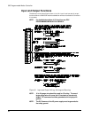
An LED indicator is associated with each input and output. The input and output
indicators are on if current is flowing in the associated line.
Figure 30 I/O Nomenclature