


22
525 Programmable Motion Controller
NOTE: Both the hardware and software position travel limits are active
if they are set up.
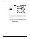
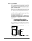
Serial Interface
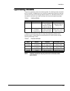
All 525 PMC's are equipped with two RS423 serial interface connectors which are
RS232C/RS422 signal compatible. The serial interface has a DIP switch selectable
baud rate ranging from 110 to 19200 bps and is connected using a simple three wire
hook-up; transmit, receive and signal ground. Transmission is accomplished using
standard printable ASCII characters. This means that the 525 PMC can also
communicate over the serial interface with a remote terminal.
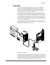
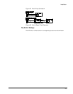
Serial A
All programming is done through the "Serial A" connector. The serial cable should
be shorter than 50ft in order to comply with RS232 specifications. However, longer
cable lengths can be possible at slower baud rates. (Less than 4800 bps).
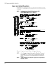
Serial B
The 525 PMC also includes a second 9 pin RS423 serial connector designated as
"Serial B", which is used for a multi-drop networking scheme to other drives. This
second connector cannot be used for programming other than in a multi-drop set up.
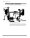
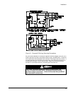
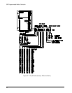
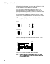
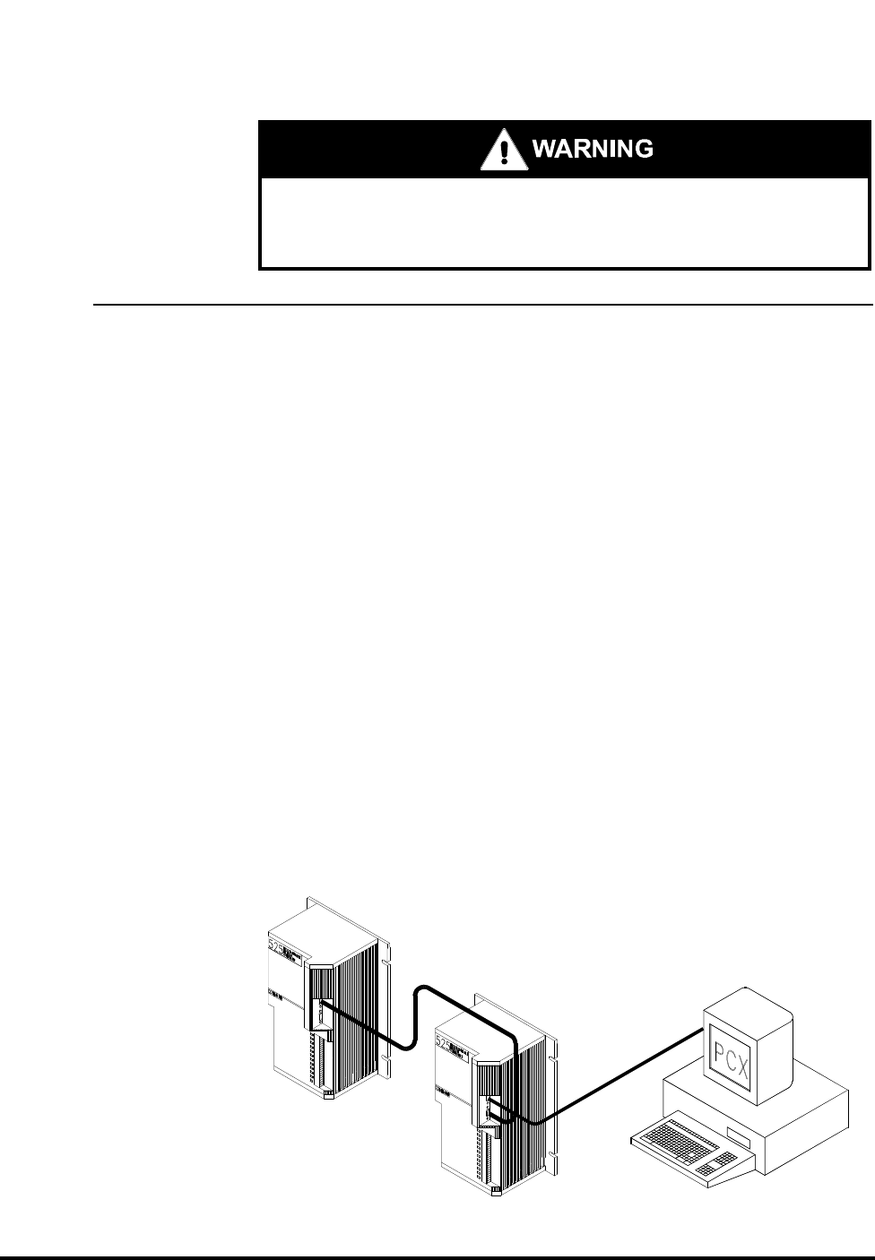
Multi-Drop Configuration
When using multi-drop configuration, the 525 PMC can automatically detect when
there are other units "down the line" and redirect its serial signals to the
appropriate drives or 525's. The serial commands are sent to the appropriate unit
based on the axis identifier dip switch settings. Each 525 PMC in a multi-drop
configuration must have a unique axis identifier code and must be set up for full
duplex mode.
The "STOP" I/O function must be held "Active" to prevent motion. if the
"Stop" I/O function is not held "Active", the operator must stop incoming
command voltage to avoid motion. Failure to follow proper safety procedures
can cause death or serious injury.