


2
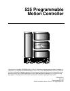
525 Programmable Motion Controller
The 525 PMC uses PCX Version 6.02 or newer for setup, calibration and
programming. A single PCX program can control multiple axes including a mixture
of Positioning Drives and 525 PMC's.
All 525 PMC gain settings are pre-programmed and can be changed from PCX
software (see PCX 6.X Operators Manual P/N 400240-01). A fine position loop
adjustment is provided on the front of the 525 PMC which allows you to fine tune
the system without requiring a personal computer. The servo amplifier and the 525
relationship is determined by a programmable command voltage to RPM ratio with
a default of 10 volts = max RPM of the motor.
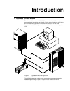
The 525 PMC is designed accept a series of application modules called "PCM"
modules. The PCMs are attached by simply plugging them onto the front of the 525
PMC. The PCM modules are designed to share the 525's power supply and include
12 additional optically isolated inputs/outputs (making a total of 24).
The 525 PMC can operate with either 115 or 220 VAC single phase power (switch
selectable). The 525 PMC includes a pulse follower mode (see "Operating Modes"
on page 4).
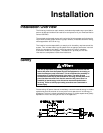
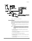
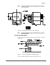
External Drive Interface
The 525 PMC is designed to be used with common servo drive systems. A perfect
match is a servo drive that has a +/- 10 volt input equalling +/- maximum velocity
and an encoder feedback signal that equates to the actual motor position.
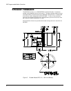
Command Signals
The 525 PMC command signal tells the servo amplifier (by the polarity and level of
the command) how fast and in what direction to move. The feedback position is
compared to the command position to determine whether the motor is doing what
it has been commanded to do. If an error between command and feedback exists,
the error is multiplied by a programmable gain and used to add or subtract the
command to the amplifier.
The input velocity scaling of the external drive must match the 525 PMC command
output scaling. By using the PCX system calibration screens, you can modify the
Calibrated Velocity and the Calibrated Velocity Command Voltage. Using these
values the 525 PMC is able to provide the proper command voltage with minimum
error.
Some drives have little or no speed regulation below 10% to 40% of the command
signal. Although this may be ok for simple velocity control, the 525 PMC must
control the speed from zero to ± full velocity. Without low speed regulation the 525
PMC cannot accelerate to the commanded speed without gross positional errors and
a possible fault condition.
The ability to accelerate or decelerate a load is a function of the external drive. The
525 PMC will linearize the velocity profile through positional feedback control. The
overall performance of the 525 PMC is tied directly to the drive's performance. The
525 PMC's ability to generate a command signal in excess of any particular drive's
capability does not mean that the 525 PMC can improve that drive's capability to
produce torque.
Special compensation of a specific amplifier may be required to accommodate a
specific application or load mismatch. Consult with the amplifier manufacturer for
specific details.