


12
525 Programmable Motion Controller
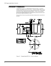
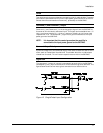
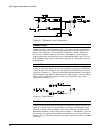
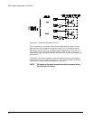
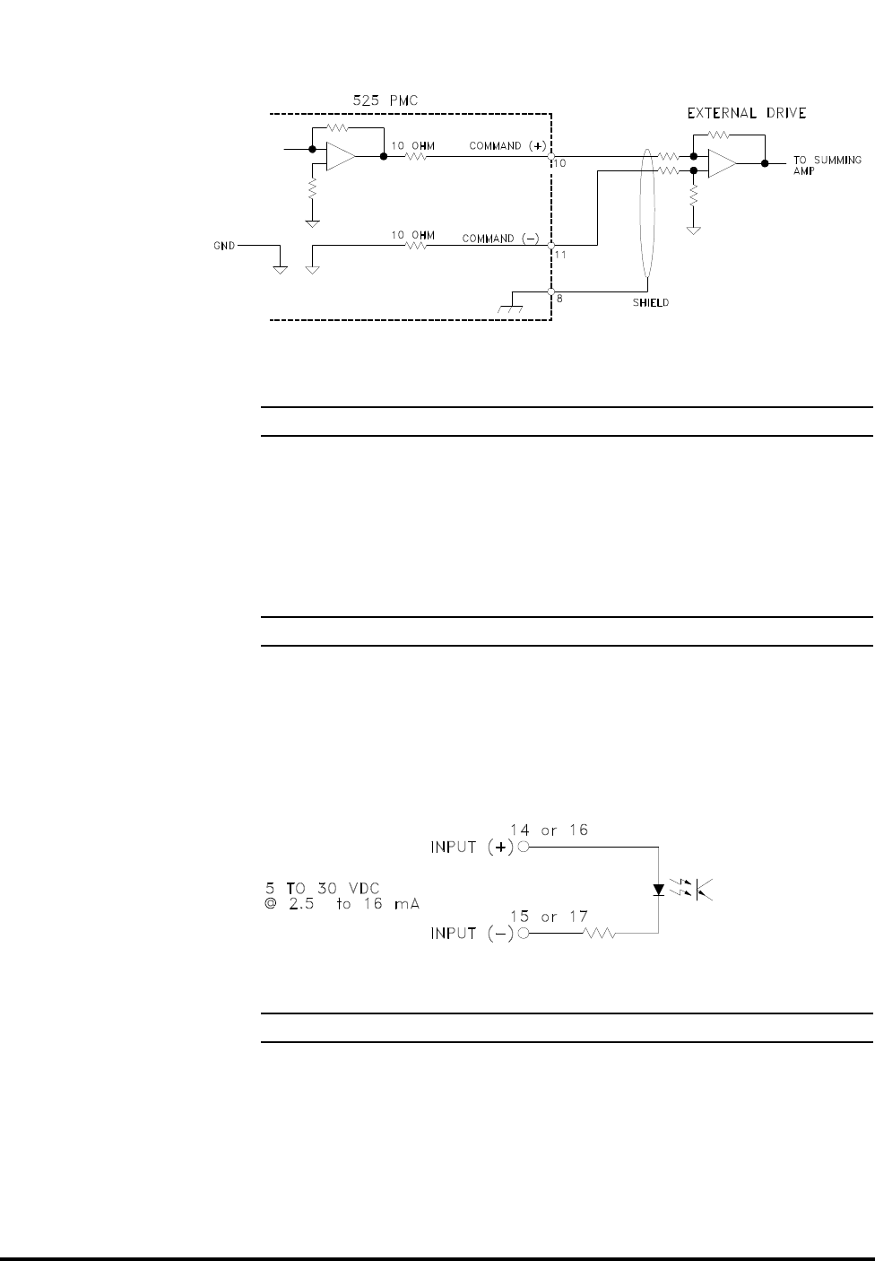
Figure 13 Differential Input Configuration
Feedback Current
Feedback current (+) and Feedback current (-) are inputs to allow the 525 PMC to
monitor the motor current via the voltage proportional to current output on the
external drive amplifier. This analog input is scaled at +/-5VDC = continuous
current and +/-10VDC = peak current. Fault times range from 4-10 seconds at
slightly greater than continuous current to 2-4 seconds at peak current. This is a
high impedance input which is referenced to logic ground. Scaling of this input is
programmable.
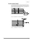
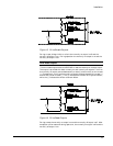
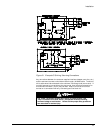
Inputs 1 & 2:
Inputs 1 & 2 allow for external drive's fault indications to be sent to the 525 PMC.
A fault on Input 1 will produce a "9" on the display of the 525 PMC and a fault on
Input 2 will produce a "11". Polarity of these inputs is programmable. If one or both
of these inputs are not used they should have their polarity set at (-) with the "Setup
Menu" of PCX (see PCX 6.X manual) or with serial commands. Typical input
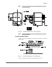
configuration is shown in 14.
Figure 14 Input Polarity
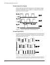
Drive Enable Outputs
The drive enable outputs allow the 525 PMC to disable the external drive during
power up, a bridge inhibit or a fault condition. The output is provided with both
normally on and normally off outputs. To utilize the normally on output connect
between drive enable (+) and normally on drive enable (-). Consequently, to utilize
the normally off output connect between drive enable (+) and normally off drive
enable (-). The (+) indicates the collector of an optical isolator while the (-) indicates
the emitter.