


25
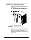
Installation
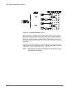
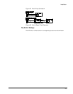
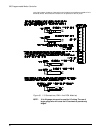
Dip Switch Function Descriptions
Baud rate switches
Switches 1, 2 and 3 of the eight position DIP switch are used to match the baud rate
of the drive to the baud rate of the programming device. If the two baud rates are
not the same, serial communication will not be possible.
Axis identifier switches
Switches 4, 5, 6, 7 and 8 are used to distinguish between drives in a multi-axis
application. This allows each axis to be programmed individually over the same
multi-drop serial cable.
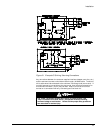
Duplex switch
Switch 1 of the four position DIP switch sets either half or full duplex mode. In half
duplex mode the serial data is not echoed back to the programming device for
conformation or display. In full duplex mode the data is echoed back to the
programming device, allowing the data to be verified. In most cases full duplex is
the preferred mode of operation.
NOTE: All drives in a multi-drop configuration must be set to full
duplex mode.
Auto line feed
Switch 2 is used to determine if a line feed character should be echoed back to the
programming device when a carriage return is received. This will alter the line
spacing on the programming monitor.
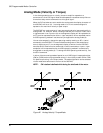
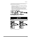
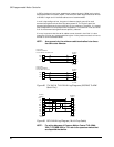
Framing information
When using serial communication, the data must be sent as a string of continuous
bits. This string of data bits must be "framed" by start and stop bits so that valid
data can be recognized. The framework which the drive will recognize is as follows:
1 start bit
8 data bits
1 stop bit
The high order data bit is ignored by the drive. A parity bit may therefore be sent
to the drive along with only seven data bits. When transmitting, the drive will
always send a zero for the eighth data bit.
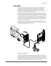
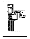
Serial Cables
The maximum allowable length of serial cable used with the 525 PMC is 50 feet.
This limitation is a result of the following statement from the EIA RS-232C
specification:
"The use of short cables (each less than approximately 50 feet or 15 meters) is
recommended; however, longer cables are permissible, provided that the resulting
load capacitance measured at the interface point and including the signal
terminator, does not exceed 2500 picofarads".