


17
Installation
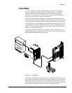
Pulse Mode
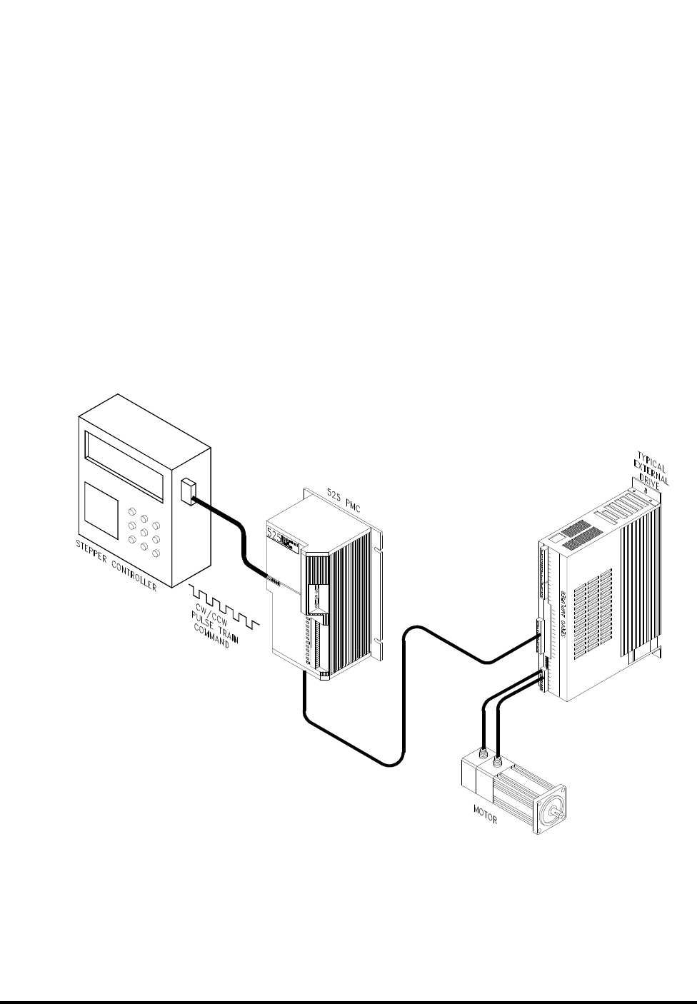
In the Pulse mode the 525 PMC responds to a serial pulse train representing
externally generated incremental position change commands. This mode is
commonly used to control DC stepper motors or numeric controlled (CNC)
machinery. The Pulse/Pulse or Pulse/ Direction operation are provided so that
pulse inputs are converted to velocity and distance.
With the Pulse/Pulse option two inputs are configured for clockwise and counter
clockwise pulses. Pulses on the CW pulse input line cause the motor shaft to rotate
CW and pulses on the CCW pulse input line cause CCW rotation of the motor shaft.
In the Pulse/Direction option the same input lines are used. However, one input line
is configured for the control pulses and the other input line is used to control the
direction. If there is no current flowing in the direction input, pulses on the pulse
input line will cause CCW rotation.
In either pulse mode, once motion is initiated with these inputs, motion in the
opposite directions can not be achieved until motion in the initiated direction has
been stopped by stopping the incoming pulses.
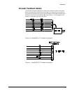
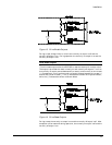
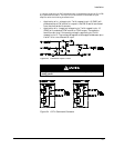
Figure 19 Pulse Mode
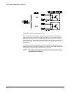
In a pulse train application the pulses are fed into the CW and CCW inputs on the
15 pin DB style command connector (pins 4, 2 and 5, 3 respectively). The inputs can
be used for sinking or sourcing current; this requires two connections per input. In
either case (sinking or sourcing), the noise immunity is improved when the normal
state of the input does not cause current to flow in the optical coupler.