


General A016-1CG-1.00-2
Full
15
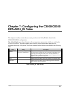
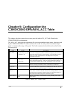
Chapter 8: Configuring the C3000/C0300
DPA A016_AI Table
This chapter describes entries the user must provide in the A016_AI table found in the
C3000/C0300 DPA configuration.
The A016_AI table provides information for system analog input points, which are used by the
C3000/C0300 DPA. It contains one record for each system analog input point to customize the
usage of the point. The fields contained in the table are described in the following table:
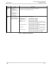
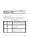
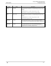
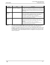
Table 9 A016_AI Table Fields
Field Range Description
Analog Input
Point
Any valid system Analog
Input point or Undefined (-
1).
The system analog input point number, which is used as the source for a
scan section. The high entry limit is confined to the highest system analog
input point configured in the system. Entering -1 causes the LRU to always
return a zero value for this point, as it is not mapped to a real system analog
input point.
Conversion
Mode
Bipolar 2’s complement
Bipolar sign/magnitude
Unipolar
The conversion mode specific to the system analog input point associated
with this record entry. It can be one of three modes, as follows:
Bipolar 2's complement (11 bits + sign)
Bipolar sign/magnitude (11 bits + sign)
Unipolar (12 bits, no sign)
Range
0 to 5000 The range used in converting the value of the system analog input point
associated with this record entry to a C3000/C0300 protocol value via the
formula:
C3000/C0300 value = (AI value * range / divisor) + offset
The typical entry is 2047, the full scale of the C3000/C0300 protocol for a
Bipolar analog value.