


Rev 1.00 7 Document 900.0399
09/05
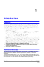
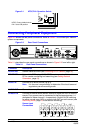
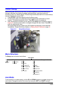
Figure 2-1 NTSC/PAL Operation Switch
Connecting Peripheral Equipment
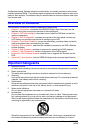
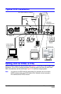
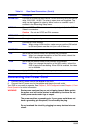
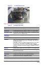
Figure 2-2 shows the rear panel connections. Refer to Table 2-1 to connect your network
system components.
Figure 2-2 Rear Panel Connections
Table 2-1 describes the rear panel connections as shown in Figure 2-2 from left to right.
Table 2-1 Rear Panel Connections
Connector Description
RS-422/485 Remote camera control (see Controlling a PTZ Camera, page 18).
ETHERNET Network the DVR using 10/100 MB Ethernet connector. Network to a
PC for remote monitoring and searching (see Setting Network
Parameters, page 19).
AUDIO IN Connect to an audio source (up to 4).
Note It is the user’s responsibility to determine if the local laws and
regulations permit recording audio.
AUDIO OUT Connect to an amplifier.
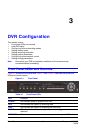
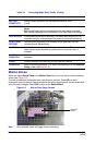
SENSOR IN Connect to external alarm sensor devices to signal the DVR to react to
events. Four sensors can be connected to the equipment sensor 1-4
dedicated to Video channel 1-4 respectively. Simple On/Off switching
for either normal open (NO) or normal close (NC) on each sensor (see
Recording Mode, page 13 to set sensor recording).
NTSC: Factory default shown
PAL: Set to ON position
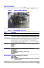
1234OUT
1234
In 1
GND 1 GND 2 GND 3 GND 4
In 2 In 3 In 4
OUT
Sensor Input
Connections
ALARM