


Rev 1.00 8 Document 900.0399
09/05
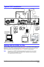
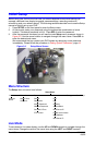
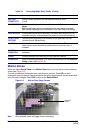
Connecting the Power Cord
1. Connect the DC power cord of the adapter to the DVR.
2. Connect the AC power cord to the adapter and then to the wall outlet.
Your DVR is now ready to operate. See Chapter 3, DVR Configuration and Chapter 4, Front
Panel Operation for more information.
WARNING! Route power cords so they are not a tripping hazard. Make certain
the power cord will not be pinched or abraded by furniture. Do not
install power cords under rugs or carpet.
The power cord has a grounding pin. If your power outlet does not
have a grounding pin receptacle, do not modify the plug.
Do not overload the circuit by plugging too many devices into one
circuit.
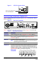
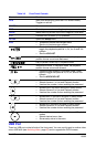
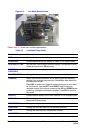
ALARM OUT Connect to an external alarm device. On/off switching using an internal
relay, 0.5A/125V, 1A/30V. The relay is open when not triggered. The
relay can be triggered to close by either motion or a sensor input, if
enabled in the Recording Setup menu.
VIDEO IN Connect NTSC or PAL camera coaxial outputs (up to 4) to the BNC
Video In connectors.
Caution Do not mix NTSC and PAL cameras.
VIDEO OUT Connect to a monitor.
RS-232 For engineering use only.
VGA Connect to a VGA monitor.
Note When using a VGA monitor, make sure you set the VGA switch
to ON and power reset the unit (turn unit off then on).
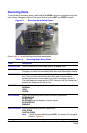
SWITCHES
PAL Set to the ON position when PAL cameras are connected.
Note When you change the position of the PAL switch, reboot the
DVR to apply the new setting.
VGA Set to the ON position when a VGA monitor is connected.
Note When you change the position of the VGA switch, reboot the
DVR to apply the new setting. When VGA is enabled, the video
out is disabled.
DC 12V Apply 12 VDC using the DC switching adapter supplied.
Table 2-1 Rear Panel Connections (Cont’d)
Connector Description