Intel® ICH5 AC ’97 Controller Theory of Operation
R
18 AC ’97 Programmer’s Reference Manual
Drivers can distribute output and input data in appropriate slots associated with available codec(s).
For example a 6-channel data stream can be separated into three, 2-channel codec streams as long
as the codecs are programmed to decode the appropriate slot output stream (SDATA_OUT).
Similarly ICH5 provides two stereo PCM input channels as well as two microphone mono input
DMA channels. These allow for separate input streams for stereo PCM and microphone recording
from two different codecs simultaneously.
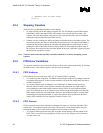
Software should match sample rates, when two codecs are teamed together. The codecs must have
matching vendors, types, and be explicitly supported in software. Essentially, audio codecs must
be programmed with a common sample rate. The selection of a common sample rate is based on
each codec’s capabilities, as detailed in Section 3.5.3.
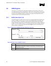
3.1.3 BIOS PCI Configuration
The ICH5 AC ’97 controller, as previously indicated, exposes two PCI functions in the ICH5 (Bus
0, Device 31h). This allows for driver differentiation between these capabilities in the component.
• Function 5: ICH5 AC ’97 audio controller
• Function 6: ICH5 AC ’97 modem controller
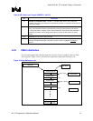
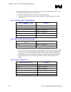
As PCI devices there are a number of registers that are required to be initialized to enable these
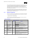
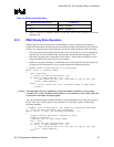
functions. The following table summarizes these requirements.
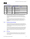
Table 3. Audio Registers
Device 31 Function 5 Audio
Offset Register Default Comments
04h-05h Command (COM) 0000h
Bit 2: Bus Master Enable
Bit 1: Memory Space Enable
Bit 0: When enable in 41h I/O Space Enable
10h-13h Native Audio Mixer Base
Address (NAMBAR)
00000001h When enable in 41h Address in the 64- K I/O space that allows
256 bytes of registers not in conflict with any other set
14h - 17h Native Audio Bus
Mastering Base Address
(NABMBAR)
00000001h When enable in 41h Address in the 64-K I/O space that allows
256 bytes of registers not in conflict with any other set
18h – 1Bh Memory Audio Mixer
Base Address (MMBAR)
00000000h Address in the 4-GB memory space that allows 512 bytes of
registers not in conflict with any other set
1Ch – 1Fh Memory Bus Master
Base Address Register
(MBBAR)
00000000h Address in the 4-GB memory space that allows 512 bytes of
registers not in conflict with any other set
3Ch Interrupt Line (INTLN) 00h A hardware interrupt (0-Fh) that follows value assigned to PIRQB#.
Has not effect on ICH5 it is used to indicate software the IRQ value
assigned to the device.
41h CFG Configuration 00h When cleared, the I/O space BARs at offset 10h and 14h become
read only registers. This is the default state for the I/O BARs.
Initialize by BIOS when backward I/O Bar compatibility is required
Memory BARs are always enabled.


