Intel® ICH5 AC ’97 Controller Theory of Operation
R
22 AC ’97 Programmer’s Reference Manual
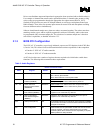
The following steps describe the driver initialization process for a single DMA engine. The same
process should be repeated for each DMA engine.
1. Create the buffer descriptor list structure in non-pageable memory.
2. Write the Buffer Descriptor List Base Address register with the base address of the buffer
descriptor list.
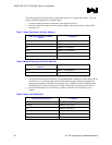
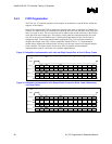
Table 7. Audio Descriptor List Base Address
Audio Buffer Descriptor List Base
Address
I/O Address:
PCM IN MBBAR + 00h (PIBAR)
PCM OUT MBBAR + 10h (POBAR)
MIC MBBAR + 20h (MCBAR)
MIC 2 MBBAR + 40h (M2DBAR)
PCM2 IN MBBAR + 50h (PI2BAR)
SPDIF MBBAR + 60h (SPBAR)
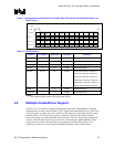
Table 8. Modem Descriptor List Base Address
Modem Buffer Descriptor List Base
Address
I/O Address:
Line IN MBAR + 00h (MIBDBAR)
Line OUT MBAR + 10h (MOBDBAR),
3. Set up the buffer descriptors and their corresponding buffers. Buffers are usually passed to the
device driver as a list of descriptors that reference physical pages. These lists describe the
physical page numbers associated with the pages in the virtual audio buffer. Multiple buffer
descriptors may be required to represent a single virtual buffer passed to the device driver
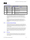
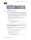
4. Once buffer descriptors are set in memory, software writes the Last Valid Index (LVI)
register.
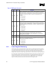
Table 9. Audio Last Valid Index
Audio Last Valid Index (LVI) I/O Address:
PCM IN MBBAR + 05h (PILVI),
PCM OUT MBBAR + 15h (POLVI),
MIC MBBAR + 25h (MCLVI)
MIC 2 MBBAR + 45h (M2LVI)
PCM2 IN MBBAR + 55h (PI2LVI)
SPDIF MBBAR + 65h (SPLVI)


