Independent Input Channels Capability
R
50 AC ’97 Programmer’s Reference Manual
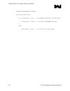
Bit Description
11 Reserved
3
Steer Enable (SE): When set, the SDATA_IN lines are treated separately and not OR’d together before
being sent to the DMA engines. When cleared, the SDATA_IN lines are OR’d together, and the
“Microphone In 2” and “PCM In 2” DMA engines are not available.
2 Reserved
1:0
Last Codec Read Data Input (LDI): When a codec register is read, this indicates which SDATA_IN the
read data returned on. Software can use this to determine how the codecs are mapped. The values
are:
00 SDATA_IN0
01 SDATA_IN1
10 SDATA_IN2
11 Reserved
Software must follow the following steps to determine the codec topology:
1. Determine codec present by reading the codec ready bits GLOB_STA Global Status Register.
MBBAR + 30h: SDATA_IN Map Register.
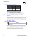
Table 28. Codec Ready Bits
Bit Description
28 Tertiary Codec Ready (TRI) – RO. Provides the state of codec ready bit on SDATA_IN[2]
9 Secondary Codec Ready (TRI) – RO. Provides the state of codec ready bit on SDATA_IN[1]
8 Primary Codec Ready (PRI) – RO. Provides the state of codec ready bit on SDATA_IN[0]
2. Once codec present is determined, software will determine the ID of the codec attached to
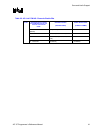
each SDATA_IN line in used by reading any codec register at codec ID 00, 01 or 10. As
indicated in Table29below and determine the returning SDATA_IN line by reading bits 1:0 in
SDATA_IN Map registers as shown in Table 27. SDATA_IN Map, above.
Table 29. MMBAR: Mixer Base Address Register
Codec ID 00 (offset) Codec ID 00 (Offset) Codec ID 00 (Offset)
00h to 7Fh 80h to FFh 100-7Fh
3. Base on the codec assignment and the specific application software will map the specific
DMA engines to the appropriate SDATA_IN[0:2] lines by programming [7:6] for PCM/MIC
and [5:4] for PCM/MIC2 in SDATA_IN MAP register as per Table 27.
4. Finally software will enable the steering mechanism by asserting bit [3] in SDATA_IN Map
register before initiating a data transfer.


