R
AC ’97 Programmer’s Reference Manual 5
Figures
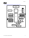
Figure 1. Block Diagram of Platform Chipset with Intel
®
ICH5 Component ......................13
Figure 2. Intel
®
ICH5 AC ’97 Controller Connection to Its Companion Codecs ................14
Figure 3. Generic Form of Buffer Descriptor (One Entry in the List).................................20
Figure 4. Buffer Descriptor List .........................................................................................21
Figure 5. Compatible Implementation with Left and Right Sample Pair in Slot 3/4 Every
Frame.........................................................................................................................26
Figure 6. Compatible Implementation with Sample Rate Conversion Slots 3 and 4
Alternating over Next Frame...................................................................................... 26
Figure 7. Incompatible Implementation of Sample Rate Conversion with Repeating Slots
over Next Frames ......................................................................................................27
Tables
Table 1. Applicable Components ........................................................................................7
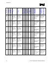
Table 2. Audio Features Distribution Matrix ......................................................................12
Table 3. Audio Registers...................................................................................................18
Table 4. Modem Registers................................................................................................19
Table 5. BD Buffer Pointer (DWORD 0: 00-03h) ..............................................................20
Table 6. BD Control and Length (DWORD 1: 04-07h)......................................................21
Table 7. Audio Descriptor List Base Address.................................................................... 22
Table 8. Modem Descriptor List Base Address................................................................. 22
Table 9. Audio Last Valid Index.........................................................................................22
Table 10. Modem Last Valid Index....................................................................................23
Table 11. FIFO Summary.................................................................................................. 27
Table 12. SDM Register Description.................................................................................28
Table 13. Dual Codecs Topologies ...................................................................................30
Table 14. Power State Mapping for Audio Single or Dual (Split) Codec Desktop
Transition ...................................................................................................................32
Table 15. Power State Mapping for Modem Single Codec Desktop Transition ................ 32
Table 16. Power State Mapping for Audio in Dual Codec Desktop Transition..................33
Table 17. Power State Mapping for Modem in Dual Codec Desktop Transition...............34
Table 18. Extended Audio ID Register..............................................................................39
Table 19. Single Codec Audio Channel Distribution .........................................................39
Table 20. Multiple Codec Audio Channel Distribution.......................................................40
Table 21. CM 4/6 –PCM Channels Capability Bits............................................................40
Table 22. AC-Link PCM 4/6 -Channels Enable Bits..........................................................41
Table 23. Sample Capabilities...........................................................................................43
Table 24. PCM Out Mode Selector ...................................................................................43
Table 25. Global Control Register S-P/DIF Slot Map Bits.................................................45
Table 26. Topology Descriptor ..........................................................................................49
Table 27. SDATA_IN Map.................................................................................................49
Table 28. Codec Ready Bits..............................................................................................50
Table 29. MMBAR: Mixer Base Address Register ............................................................50


