Intel® ICH5 AC ’97 Controller Theory of Operation
R
AC ’97 Programmer’s Reference Manual 33
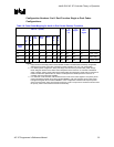
Configuration Numbers 3 to 6: Dual Function Single or Dual Codec
Configurations:
Table 16. Power State Mapping for Audio in Dual Codec Desktop Transition
PR<0:5> + (EAPD)
+12 +5
from
+12
+3.3
Digital
+3.3
Vaux
Digital
Comments
E
A
P
D
C
L
K
AC-
Link
Mixer
Vref.
Mixer D
A
C
A
D
C
Device
State
7 5 4 3 2 1 0
D0 0 0 0 0 0 0 0 On On On On All on
D1 0 0 0 0 0 1 1 On On On On -DAC, -ADC
D2 1 0 0 0 1 1 1 On On On On -Mix, -Amp
D3 1 0 0 1 1 1 1 Off Off Off On -Clock, -Vref
NOTES:
1. PR(4) link down and PR(5) internal clocks disable are NOT recommended for desktop configuration.
Setting these to power control bits could affect modem operation in an AC + MC configuration.
2. In a mobile system configuration, PR(4) and PR(5) could be used to provide further power savings.
Driver designers should use D3 state codec semaphores in the ICH5 AC ’97 controller to determine
audio or modem codecs power status before setting PR(4) and PR(5) bits. Please refer to ICH5 AC ’97
External Architecture Specification for details. The miniport driver developed for the ICH5 AC ’97
controller does not provide this capability.
3. In a dual audio codec transition, PR bits must be set in both of the codec registers. The primary audio
power management register set is always located MMBAR + 26h, the secondary audio codec power
management register set is located at MMBAR + A6h. Configuration software must sequence power
down to the secondary codec first and then the primary codec. The process is reversed at resume when
the primary codec is first restored and then the secondary.


