


– 16 –
Controls and their functions
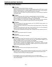
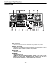
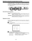
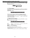
<Connector area>
5 TIME CODE IN connector
This is the connector for recording the external time code on the tape.
6 TIME CODE OUT connector
The playback time code is output from this connector during playback.
During recording, the time code generated by the internal time code generator is output.
7 CUE IN connector
The analog signal to be recorded on the CUE track is supplied to this connector. The audio
signals from a microphone can also be recorded by selecting the –60dB input mode on the
setup menu No. 705 (CUE IN LV).
8 CUE OUT connector
The analog signal recorded on the CUE track is output from this connector.
9 MONITOR OUT connector
During playback, the playback signals from the CUE track or PCM audio signal CH1, CH2,
CH3, CH4, CH5, CH6, CH7 and CH8 are output from this connector.
: ANALOG AUDIO IN connectors
These are the input connectors for the analog audio signals (CH1, CH2, CH3, CH4).
; ANALOG AUDIO OUT connectors
These are the output connectors for the analog audio signals (CH1, CH2, CH3, CH4).
<<
<<
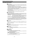
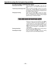
< HD SERIAL DIGITAL COMPONENT AUDIO VIDEO IN/OUT connectors
These are the input and output connectors for the HD digital component audio and video
signals that comply with the SMPTE 292M standard.
The TC, menu or other information is output from the HD SDI OUT3 connector with the
information superimposed onto the signals.
= =
= =
= SDTI IN/OUT connectors (optional accessory)
These are the input/output signal connectors for the compressed data that complies with
the SMPTE 305M standard.
>>
>>
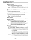
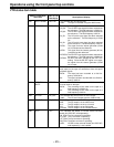
> SD SERIAL DIGITAL COMPONENT AUDIO VIDEO OUT connectors
These are the output connectors for the digital component audio and video signals that
comply with the SMPTE 259M-C, 272M and 294M standards.
The signals are output during the playback of compatible DVCPRO25M, 50M, DV or
DVCAM format tapes or during down-conversion output (optional accessory).
The TC, menu or other information is output from the SD SDI OUT3 connector with the
information superimposed onto the signals.
??
??
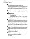
? ANALOG COMPOSITE VIDEO OUT connectors
These are the output connectors for the analog composite video signals.
The signals are output during the playback of compatible DVCPRO25M, 50M, DV or
DVCAM format tapes or during down-conversion output (optional accessory).
Video signals with information superimposed onto them can be output from the VIDEO
OUT3 connector.
Whether information is to be superimposed or not (ON/OFF) is selected by setting the
setup menu No.005 (SUPER) item.
The VIDEO OUT2 connector can also be used as the WFM (waveform) OUT connector.
TC, CTL, VIDEO, RF L/R and ENV L/R are the signals which can be selected on the
menu.