


9
RQT9431
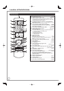
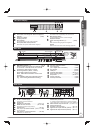
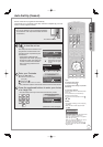
The Unit’s Display
6
bk
879
PLAY
EXT-L COPY
SD USB
HDDSDVD
2345
1
1
SD card slot indicator
2
Linked timer recordings with external equipment
indicator .................................................... (➔ 62)
3
USB port indicator
4
Copying indicator
5
Disc indicator
This indicator lights up when a disc is inserted.
6
Drive (HDD, DVD or SD) indicator
Select “DVD” for any discs. DVD indicator will light up.
7
Remote control signal indicator
This flashes when it is operated by the remote control.
8
Main display section
Current time/playback counter, various messages
9
Playback indicator
bk
Timer recording indicator (
z
) ................... (➔ 29
)
On:
When a timer recording programme is registered.
Flashes:
When the unit cannot record a timer recording programme.
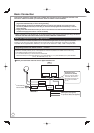
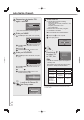
Main Unit
1
Standby/on switch (
^
/I) .............................(➔ 13)
Press to switch the unit from on to standby mode
or vice versa. In standby mode, the unit is still
consuming a small amount of power.
2
Recording indicator (“REC1”, “REC2”)
Red indicator light during recording.
REC1, REC2 shows the status of one or twin
recording.
REC indication flash during Recording Pause.
(e.g., when starting Guide LINK recording)
3
Disc tray open/close button ..........................(➔ 26)
4
DV IN terminal
(for a digital video camcorder) .....................(➔ 63)
5
SD card slot ................................................(➔ 118)
6
USB port .....................................................(➔ 118)
7
Channel select button .............................(➔ 24, 27)
8
Start recording button ...................................(➔ 27)
9
Stop button .............................................(➔ 26, 27)
bk
Play/✕1.3 button ...........................................(➔ 26)
bl
AV3 input terminals .......................................(➔ 63)
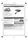
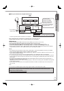
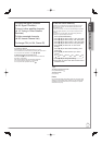
Rear Panel
LAN
PCM/BITST EAM
)
COMPONENT
AV4 IN
OUT
R AUDIO L
S VIDEO
VIDEO
AC IN
DISH
IN 1
DISH
IN 2
Y
P
B
P
R
AV OUT
OPTICAL
DIGITAL
AUDIO
OUT
AV1
(
T
AV2
(
EX
18V
350mA max
13V/
100BASE TX
10BASE T
COAXIA
V DEO OUT
DMR XS350EBK
PR000001010
SER NO
465897
bo
312 bmblbk bn
1
Serial number
2
AC IN~ = Power supply
Connection for the AC mains lead
3
Cooling fan
4
Satellite input terminals .....................(➔ 10, 11)
5
HDMI AV OUT terminal ...................(➔ 10, 109)
Digital audio and video output terminal
6
LAN terminal ......................................... (➔ 112)
7
AV1 (TV) 21-pin Scart termina
l ...(➔ 10, 11, 109)
TV set connection
8
AV2 (EXT) 21-pin Scart terminal ...........(➔ 109)
Connection of an external unit
9
COMPONENT VIDEO OUT (PROGRESSIVE/
INTERLACE) terminals .........................(➔ 110)
Y = Luminance signal (brightness), P
B
= Chrominance signal
(colour difference), P
R
= Chrominance signal (colour difference)
bk
AUDIO/VIDEO output terminals ....(➔ 110, 111)
bl
AV4 input terminals
bm
S VIDEO output terminal .......................(➔ 110)
bn
Digital audio output terminal (optical) ....(➔ 111)
bo
Digital audio output terminal (coaxial).....(➔ 111)
For information about the 21-pin Scart terminal (➔ 109)
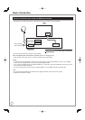
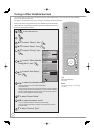
Quick Start Guide
STEP 1
Pull to
flip down
the front
panel.
The unit’s display
Remote control
signal sensor
1
3
2
67 bk54bl89
Disc tray