


Service Modes, Error Codes, and Fault Finding
EN 20 Q549.2E LA5.
2009-May-08
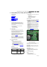
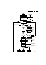
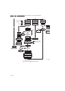
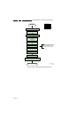
Figure 5-5 “Off” to “Semi Stand-by” flowchart (part 2)
Yes
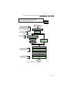
MIPS reads the wake up reason
from standby µP.
Semi-Standby
initialize tuner, Master IF and channel
decoder
Initialize video processing IC's
Initialize source selection
initialize AutoTV
3-th try?
No
Blink Code as
error code
Bootscript ready
in 1250 ms?
Yes
No
Enable Alive check mechanism
Wait until AVC starts to
communicate
SW initialization
succeeded
within 20s?
No
Switch Standby
I/O line high.
RPC start (comm. protocol)
Set I²C slave address
of Standby µP to (60h)
Yes
Disable all supply related protections and
switch off the +3V3 +5V DC/DC converter.
switch off the remaining DC/DC
converters
Wait 5ms
Switch AVC PNX8541
in reset (active low)
Wait 10ms
Switch the NVM reset
line HIGH.
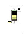
Flash to Ram
image transfer succeeded
within 30s?
No
Yes
Code =
Layer1: 2
Layer2: 53
Code =
Layer1: 2
Layer2: 15
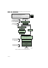
Initialize Ambilight with Lights off.
Timing need to be updated if
more mature info is available.
Timing needs to
be updated if more
mature info is
available.
Timing needs to be
updated if more
mature info is
available.
Downloaded
successfully ?
Download firmware into the channel
decoder
Third try? No
No
Yes
Log channel decoder error:
Layer1: 2
Layer2: 37
Yes
Initialize audio
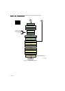
Enter protection
Release reset MPEG4 module:
BOLT-ON-IO: High
MPEG4 module will start booting
autonomously.
Wait 3000 ms
Start alive IIC polling
mechanism
POR polling positive?
yes
No
Log SW event:
STi7100PorFailure
Wait 200 ms
POR polling positive ?yes
No
bootSTi7100PorFailure:
Log HW error
Layer1: 2
Layer2: 38
and generate cold boot
Alive
polling
Log SW event
STi7100AliveFailedError
and generate fast cold reboot
eventually followed by a cold
reboot.
NOK
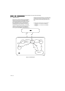
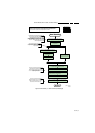
Reset-system is switched HIGH by the
AVC at the end of the bootscript
AVC releases Reset-Ethernet when the
end of the AVC boot-script is detected
This cannot be done through the bootscript,
the I/O is on the standby µP
Reset-system is connected to USB
From I_17660_125a.eps From I_17660_125a.eps
-reset,
4to1HDMI Mux and channel decoder.
Reset-Audio and Audio-Mute-Up are
switched by MIPS code later on in the
startup process
Reset-system is switched HIGH by the
AVC at the end of the bootscript
AVC releases Reset-Ethernet when the
end of the AVC boot-script is detected
Reset-Audio and Audio-Mute-Up are
switched by MIPS code later on in the
startup process
Switch on the display in case of a LED backlight
display by sending the TurnOnDisplay(1) (I²C)
command to the PNX5100
In case of a LED backlight display, a LED DIM panel is
present which is fed by the Vdisplay. To power the LED DIM
Panel, the Vdisplay switch driven by the PNX5100 must be
closed. The display startup sequence is taken care of by the
LED DIM panel.
I_17660_125b.eps
140308