


Service Modes, Error Codes, and Fault Finding
EN 29Q549.2E LA 5.
2009-May-08
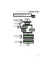
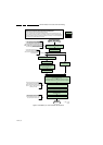
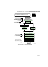
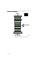
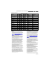
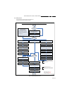
Table 5-2 Error code overview
Extra Info
• Rebooting. When a TV is constantly rebooting due to
internal problems, most of the time no errors will be logged
or blinked. This rebooting can be recognized via a ComPair
interface and Hyperterminal (for Hyperterminal settings,
see section “5.8 Fault Finding and Repair Tips
, 5.8.6
Logging). It’s shown that the loggings which are generated
by the main software keep continuing. In this case
diagnose has to be done via ComPair.
• Error 13 (I
2
C bus 3 blocked). At the time of release of this
manual, this error was not working as expected. Current
situation: when this error occurs, the TV will constantly
reboot due to the blocked bus. The best way for further
diagnosis here, is to use ComPair.
• Error 15 (PNX8543,PNX5100 doesn’t boot). Indicates
that the main processor/PNX5100 was not able to read his
bootscript. This error will point to a hardware problem
around the PNX8543 (supplies not OK, PNX 8543
completely dead, I
2
C link between PNX and Stand-by
Processor broken, etc...). When error 15 occurs it is also
possible that I
2
C1 bus is blocked (NVM). I
2
C1 can be
indicated in the schematics as follows: SCL-UP-MIPS,
SDA-UP-MIPS, SCL-1, SDA-1, SCL-2 or SDA-2.
Other root causes for this error can be due to hardware
problems from the NVM PNX5100, DDR’s and the
bootscript reading from the PNX5100.
• Error 16 (12V). This voltage is made in the power supply
and results in protection (LAYER 1 error = 3) in case of
absence. When SDM is activated we see blinking LED
LAYER 2 error = 16.
• Error 17 (Invertor or Display Supply). Here the status of
the “Power OK” is checked by software, no protection will
occur during failure of the invertor or display supply (no
picture), only error logging. LED blinking of LAYER 1
error = 3 in CSM, in SDM this gives LAYER 2 error = 17.
• Error 18 (1V2-3V3-5V too low). All these supplies are
generated by the DC/DC supply on the SSB. If one of these
supplies is too low, protection occurs and blinking LED
LAYER 1 error = 2 will be displayed automatically. In SDM
this gives LAYER 2 error = 18.
• Error 21 (PNX 5100). When there is no I
2
C communication
towards the PNX5100, the TV set will start rebooting and
display LAYER 1 error = 2. Disconnect the mains cord now
and start up the TV set with the solder path (SDM) short to
ground during start-up to activate the LAYER 2 error
blinking. Error “21” will be logged and displayed via the
blinking LED procedure after a few moments from start-up.
Remark : the rebooting can be recognized via a ComPair
interface and Hyperterminal (for Hyperterminal settings,
see section “5.8 Fault Finding and Repair Tips
, 5.8.6
Logging”). It is shown that the loggings which are
generated by the main software keep continuing. Check in
the logging for keywords like e.g. “Device error 21”.
• Error 23 (HDMI). When there is no I
2
C communication
towards the HDMI mux after start-up, LAYER 2 error = 23
will be logged and displayed via the blinking LED
procedure if SDM is switched on. It should be noted that in
case a new spare EDID MUX device is used for repair, the
initial default address must be changed from “C0” to “CE”,
to be done via ComPair.
• Error 24 (I
2
C switch). When there is no I
2
C
communication towards the I
2
C switch, LAYER 2
error = 24 will be logged and displayed via the blinking LED
procedure when SDM is switched on. Remark : this only
works for TV sets with an I
2
C controlled screen included.
• Error 25 (Boot-NVM PNX5100). Same behaviour as
described in “Error 21 (PNX5100)”.
• Error 27 (Micronas IF). When there is no I
2
C
communication towards the multi standard demodulator,
LAYER 2 error = 27 will be logged and displayed via the
blinking LED procedure if SDM is switched on.
• Error 28 (ARM ambilight). When there is no I
2
C
communication towards the ARM processor, LAYER 2
error = 28 will be logged and displayed via the blinking LED
procedure if SDM is switched on.
• Error 29 (FPGA local contrast). When there is no I
2
C
communication towards this FPGA, LAYER 2 error = 29
will be logged and displayed via the blinking LED
procedure if SDM is activated.
• Error 34 (Tuner). When there is no I
2
C communication
towards the tuner after start-up, LAYER 2 error = 34 will be
Description Layer 1 Layer 2
Monitored
by
Error/
Prot
Error Buffer/
Blinking LED Device Defective Board
I
2
C3 2 13 MIPS E BL / EB SSB SSB
I
2
C2 2 14 MIPS E BL / EB SSB/Display SSB/display
PNX doesn’t boot (HW cause)
PNX 5100 doesn’t boot
2 15 Stby µP P BL PNX8543/PNX51XX
I
2
C blocked
SSB
12V 3 16 Stby µP P BL / Supply
Inverter or display supply 3 17 MIPS E EB /
1V2, 3V3, 5V to low 2 18 Stby µP P BL / SSB
Temp protection 3 12 MIPS E EB / Display
PNX 5100 2 21 MIPS E EB PNX5100 SSB
HDMI mux 2 23 MIPS E EB TDA9996 SSB
I
2
C switch 2 24 MIPS E EB PCA9540 SSB
Boot-NVM PNX5100 2 25 MIPS E EB STM24C08 SSB
Multi Standard demodulator
(Micronas IF)
2 27 MIPS E EB DRX3616K
DRX3626K
SSB
ARM (ambilight) 8 28 MIPS E EB NXP LPC2103 AL module or DC/DC
FPGA (Local contrast) 2 29 MIPS E EB Altera SSB
Tuner 2 34 MIPS E EB UV1783S/HD1816 SSB
Fan I2C expander 7 41 MIPS E EB PCA9533 FAN module
T° sensor 7 42 MIPS E EB LM 75 T° sensor
FAN 1 7 43 MIPS E EB FAN
FAN 2 7 44 MIPS E EB FAN
Main NVM 2 / MIPS E X STM24C128 SSB
PNX doesn’t boot (SW cause) 2 53 Stby µP E BL PNX8543 SSB
Display (only 56PFL9954H) 5 64 MIPS E BL / EB Altera Display