


Circuit Descriptions
EN 52 Q549.2E LA7.
2009-May-08
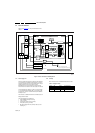
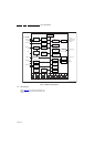
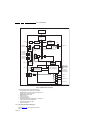
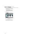
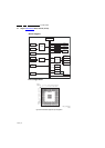
Figure 7-14 SPI communication between ARM controller and LED drivers
The ARM controller communicates with the LED drivers (on
each AL module) via an SPI bus. For debugging purposes, the
working principle is given below:
• Data from the ARM controller is linked through the drivers,
which are connected in cascade
• SPI CLK, SPI LATCH, PROG, BLANK and PWM CLOCK
are going directly from the controller to each driver
• SPI DATA RETURN is linked from the last driver to the
controller: controller decides which driver returns data.
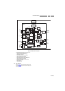
7.8.3 Temperature Control
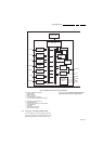
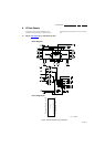
Refer to Figure 7-15
for signal interfacing between the ARM
controller and the temperature sensor on the AL boards.
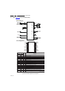
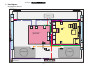
Figure 7-15 Communication between ARM controller and
temperature sensor
Each AL board is equipped with a temperature sensor. If one of
the sensors detects a temperature over the threshold, the
TEMP line is pulled LOW which results in brightness reduction.
18310_206_090318.eps
090318
Ambilight module 1 Ambilight module 2
ARM
TEMP
SENSOR
Vcc
Pu ll-upPull-upPull-up
TEMP
SENSOR
Vcc
Ambilight module N
TEMP
SENSOR
Vcc