


Service Modes, Error Codes, and Fault Finding
EN 27Q549.2E LA 5.
2009-May-08
5.4 Service Tools
5.4.1 ComPair
Introduction
ComPair (Computer Aided Repair) is a Service tool for Philips
Consumer Electronics products. and offers the following:
1. ComPair helps to quickly get an understanding on how to
repair the chassis in a short and effective way.
2. ComPair allows very detailed diagnostics and is therefore
capable of accurately indicating problem areas. No
knowledge on I
2
C or UART commands is necessary,
because ComPair takes care of this.
3. ComPair speeds up the repair time since it can
automatically communicate with the chassis (when the uP
is working) and all repair information is directly available.
4. ComPair features TV software up possibilities.
Specifications
ComPair consists of a Windows based fault finding program
and an interface box between PC and the (defective) product.
The ComPair II interface box is connected to the PC via an
USB cable. For the TV chassis, the ComPair interface box and
the TV communicate via a bi-directional cable via the service
connector(s).
The ComPair fault finding program is able to determine the
problem of the defective television, by a combination of
automatic diagnostics and an interactive question/answer
procedure.
How to Connect
This is described in the chassis fault finding database in
ComPair.
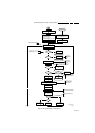
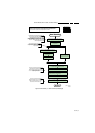
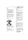
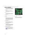
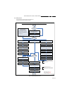
Figure 5-12 ComPair II interface connection
Caution: It is compulsory to connect the TV to the PC as
shown in the picture above (with the ComPair interface in
between), as the ComPair interface acts as a level shifter. If
one connects the TV directly to the PC (via UART), ICs will be
blown!
How to Order
ComPair II order codes:
• ComPair II interface: 3122 785 91020.
• Software is available via the Philips Service web portal.
• ComPair UART interface cable for Q54x.x.
(using 3.5 mm Mini Jack connector): 3138 188 75051.
Note: While encounting problems, contact the local support
desk.
5.4.2 Memory and Audio Test
With this tool you can test the memory of the PNX8543, as well
if the PNX5100 is enabled and audio-testing.
What is needed?
– An USB-stick
– “TESTSCRIPT Q549”. Downloadable from the Philips
Service website from the section “Software for Service
only”
– A ComPair/service cable (3138 188 75051).
Procedure
Create a directory “JETTFILES” under the root of the USB-stick
– Place “MemTestTV543.bin” and “autojett.bin” (available in
“TESTSCRIPT Q549”) under the directory “JETTFILES”
– Install the computer program “BOARDTESTLOGGER”
(available in “TESTSCRIPT Q549”) on the PC
– Connect a “ComPair/service”-cable from the service-
connector in the set, into the “multi function” jack at the
front of the ComPair II box :
Required settings in ComPair :
- start up the ComPair application.
- Select the correct database (open file “Q549.2E LA”, this
will set the ComPair interface in the appropriate mode).
- Close ComPair
– Start up the program “BOARDTESTLOGGER” and select
“COMx”
– Put the USB stick into the TV and start up the TV while
pressing the “i+”-button on a Philips DVD RC6 remote
control (it’s also possible to use a TV remote in “DVD”-
mode)
– On the PC the memory test is shown now. This is also
visible on the TV screen.
– In “BOARDTESTLOGGER” an option “Send extra UART
command” can be found where you can select “AUD1”.
This command generates hear test tones of 200, 400,
1000, 2000, 3000, 5000, 8000 and 12500Hz.
5.5 Error Codes
5.5.1 Introduction
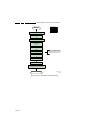
The error code buffer contains all detected errors since the last
time the buffer was erased. The buffer is written from left to
right, new errors are logged at the left side, and all other errors
shift one position to the right.
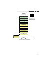
When an error occurs, it is added to the list of errors, provided
the list is not full. When an error occurs and the error buffer is
full, then the new error is not added, and the error buffer stays
intact (history is maintained).
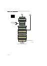
To prevent that an occasional error stays in the list forever, the
error is removed from the list after more than 50 hrs. of
operation.
When multiple errors occur (errors occurred within a short time
span), there is a high probability that there is some relation
between them.
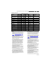
New in this chassis is the way errors can be displayed:
• There is a simple blinking LED procedure for board level
repair (home repair) so called LAYER 1 errors next to the
existing errors which are LAYER 2 errors (see Table 5-2
).
– LAYER 1 errors are one digit errors.
– LAYER 2 errors are 2 digit errors.
• In protection mode.
– From consumer mode: LAYER 1.
– From SDM mode: LAYER 2.
• Fatal errors, if I2C bus is blocked and the set reboots,
CSM and SAM are not selectable.
– From consumer mode: LAYER 1.
– From SDM mode: LAYER 2.
Important remark:
E_06532_036.eps
150208
TO
UART SERVICE
CONNECTOR
TO
UART SERVICE
CONNECTOR
TO
I
2
C SERVICE
CONNECTOR
TO TV
PC
HDMI
I
2
C only
Optional power
5V DC
ComPair II Developed by Philips Brugge
RC out
RC in
Optional
Switch
Power ModeLink/
Activity
I
2
C
ComPair II
Multi
function
RS232 /UART