


Service Modes, Error Codes, and Fault Finding
EN 31Q549.2E LA 5.
2009-May-08
loudspeakers will move slowly in one or the other direction
until the initial failure shuts the amplifier down, this cyclus
starts over and over again.
5.7.3 Important remark regarding the blinking LED indication
As for the blinking LED indication, the blinking led of LAYER 1
error displaying can be switched off by pushing the power
button on the keyboard.
This condition is not valid after the set was unpowered (via
mains interruption). The blinking LED starts again and can only
be switched off by unplugging the mains connection.
This can be explained by the fact that the MIPS can not load
the keyboard functionality from software during the start-up and
doesn’t recognizes the keyboard commands at this time.
5.8 Fault Finding and Repair Tips
Read also section “5.5 Error Codes, 5.5.4 Error Buffer, Extra
Info”.
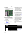
5.8.1 Ambilight
Due to degeneration process of the AmbiLights, there can be a
difference in the colour and/or light output of the spare
ambilight module in comparison with the originals ones
contained in the TV set. Via ComPair the light output can be
adjusted.
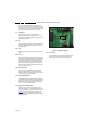
5.8.2 Audio Amplifier
The Class D-IC 7D10 has a powerpad for cooling. When the IC
is replaced it must be ensured that the powerpad is very well
pushed to the PWB while the solder is still liquid. This is needed
to insure that the cooling is guaranteed, otherwise the Class D-
IC could break down in short time.
5.8.3 CSM
When CSM is activated and there is a USB stick connected to
the TV, the software will dump the complete CSM content to the
USB stick. The file (Csm.txt) will be saved in the root of the USB
stick. If this mechanism works it can be concluded that a large
part of the operating system is already working (MIPS, USB...)
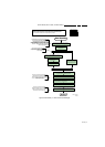
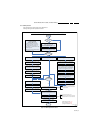
5.8.4 DC/DC Converter
Description
The onboard supply consists of 5 DC/DC converters and 4
linear stabilizers. All DC/DC converters have +12V input
voltage and deliver :
• +1V2-PNX85XX supply voltage (1.24V nominal), stabilized
close to PNX8543 chip.
• +1V2-PNX5120 supply voltage (1.26V nominal), stabilized
close to PNX5120 chip.
• +3V3 (3.34V nominal, overall 3.3 V for onboard IC’s).
• +5V (5.15V nominal) for USB and Conditional Access
Interface and +5V5-TUN for +5V-TUN tuner stabilizer.
• +33VTUN (34V nominal) for analog-only tuners.
The linear stabilizers are providing:
• +1V2-STANDBY (out of +3V3-STANDBY), 1.24V nominal.
• +1V8-PNX85XX and +1V8PNX5100 (connected via
CFH1), 1.84V nominal.
• +2V5 (WOW FPGA diversity only), 2.5V nominal.
• +5V-TUN (out of +5V5-TUN), 5V nominal.
+3V3-STANDY and +1V2-STANDBY are permanent voltages.
Supply voltages +1V2-PNX85XX and +1V2-PNX5100 are
started immediately when +12V incoming voltage is available
(+12V is enabled by STANDBY signal, active low). Supply
voltages +3V3, 2V5, +1V8-PNX5100, +1V8-PNX85XX, +5V
and +5V-TUN are switched-on directly by signal ENABLE-3V3
(active low), provided that +12V (detected via 7U40 &7U41) is
available. +12V is considered OK (=> DETECT -12V signal
becomes high and 12V/3V3 and 12V/5V DC-DC converter can
be started up) if it rises above 10V5 (typical) and doesn’t drop
below 10V (typical).
Debugging
The best way to find a failure in the DC/DC converters is to
check their start-up sequence at power-on via the mains cord,
presuming that the standby microprocessor and the external
supply are operational. Take STANDBY signal high-to-low
transition as time reference.
When +12V becomes available (maximum 1 second after
STANDBY signal goes low) then +1V2-PNX85XX and +1V2-
PNX5100 are started immediately. Then, after ENABLE-3V3
goes low, all the other supply voltages should rise within 2ms.
Tips
• When an output supply voltage is short-circuited to GND
the corresponding DC-DC converter is not
making any
audible noise, the converter switches-off immediately and
will attempt a re-start only after +12V drops and rises
again.
• Check the integrity (at least no short-circuit between drain
and source) of power MOS-FETs, especially the high-side
ones: 7U05, 7U08, 7U0D-1 and 7U0H-1 before starting the
platform in SDM mode, otherwise it can be easily
damaged.
• Switching frequency of DC-DC converters should be
around 290KHz for 12V to 1V2 DC-DC converters and
around 370KHz for 12V to 3V3 and 12V to 5V DC-DC
converters.
5.8.5 Exit “Factory Mode”
When an “F” is displayed in the screen’s right corner, this
means the set is in “Factory” mode, and it normally
happens after a new SSB is mounted. To exit this mode, push
the “VOLUME minus” button on the TV’s local keyboard for 10
seconds (this disables the continuous mode).
Then push the “SOURCE” button for 10 seconds until the “F”
disappears from the screen.
5.8.6 Logging
When something is wrong with the TV set (f.i.the set is
rebooting) you can check for more information via the logging
in Hyperterminal. The Hyperterminal is available in every
Windows application via Programs, Accessories,
Communications, Hyperterminal. Connect a “ComPair UART”-
cable (3138 188 75051) from the service connector in the TV to
the “multi function” jack at the front of ComPair II box.
Required settings in ComPair before starting to log :
- Start up the ComPair application.
- Select the correct database (open file “Q549.2E LA”, this will
set the ComPair interface in the appropriate mode).
- Close ComPair
After start-up of the Hyperterminal, fill in a name (f.i. “logging”)
in the “Connection Description” box, then apply the following
settings:
1. COMx
2. Bits per second = 115200
3. Data bits = 8
4. Parity = none
5. Stop bits = 1
6. Flow control = none
During the start-up of the TV set, the logging will be displayed.
This is also the case during rebooting of the TV set (the same
logging appears time after time). Also available in the logging
is the “Display Option Code” (useful when there is no picture),