


Circuit Descriptions
EN 45Q549.2E LA 7.
2009-May-08
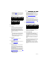
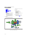
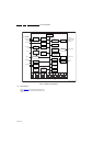
7.3 Front-End
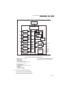
The Front-End consist of the following key components:
• Tuner HD1816AF
• SAW filter 36M125
• IF demodulator DRX3926K
• AGC amplifier UPC3221GV.
Below find a block diagram of the front-end application.
Figure 7-4 Front-End block diagram
The DRX3926K is a multi-standard demodulator supporting
DVB-C, DVB-T and analogue standards. The demodulated
digital stream is fed into the parallel transport stream data ports
of the PNX8543. The demodulated analogue signal in the form
of CVBS is connected to the analogue video CVBS/Y input
channel, while the SIF is connected via the SSIF2 positive input
port.
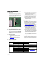
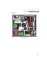
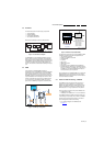
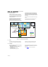
7.4 HDMI
In this platform, the TDA9996 HDMI multiplexer is
implemented. Only for one HDMI input, a separate EEPROM is
implemented to store the EDID values. For the other HDMI
inputs, the EDID contents are no longer stored in a separate
EEPROM, but directly in the multiplexer. Each input has its own
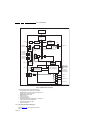
physical subaddress: the first 253 bytes are common, where
the last 3 bytes define the specific input. The EDID contents
are, at +5V power-up, downloaded to RAM. The following
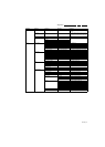
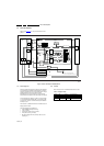
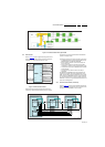
figures show the HDMI input configuration and EDID control.
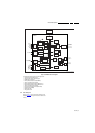
Figure 7-5 HDMI input configuration
Figure 7-6 EDID control (embedded EDID)
The delta’s with respect to the use of the TDA9996 as HDMI
multiplexer compared with earlier chassis/platforms are:
• +5V detection mechanism
• Stable clock detection mechanism
• Integrated EDID
• RT control
• HPD control
• TMDS output control
• CEC control
• New hotplug control for PNX8543 for 5th HDMI input
• New EDID structure: EDID stored in TDA9996, therefore
there are no EDID pins on the SSB. Only in the event of a
5th HDMI input, an additional EEPROM is foreseen, as
was implemented in previous platforms.
After replacement of the TDA9996 HDMI mux, the default I
2
C
address should be reprogrammed from C0 to CE, and the
HDMI EDIDs should be reprogrammed as well. Both actions
should be executed via ComPair.
7.5 Video and Audio Processing - PNX8543
The PNX8543 is the main audio and video processor (or
System-on-Chip) for this platform. It is a member of the
PNX85xx SoC family (described in earlier chassis) with the
addition of the MPEG4 functionality; the separate STi710x
MPEG4 decoder is no longer implemented in this platform.
Some more delta’s compared to the previous PNX85xx are:
• 2 HDMI inputs (A & B)
• HDMI deep colour RGB/YCbCr 4:4:1 10/12 bit detection.
The PNX8543 handles the digital and analogue audio- and
video decoding and processing. The processor is a MIPS32
general purpose CPU and a 8051-based TV controller for
power management and user event handling.
• For a functional diagram of the PNX8543, refer
to Figure 7-7
.
18440_211_090227.eps
090227
I2C-TUNER
IF-AGC
NXP Hybrid
Tuner
SAW
Filter
IF Amplifier DRX3926K PNX8543
I2C-SSB
CVBS
2nd SIF
TS
TDA9996
1P06
1P04
1P03
1P02
1P 05
HDMIA-RX
ARX
BRX
CRX
DRX
HDMIB-RX
PNX8543
D
C
A
B
Out
1M96
A B
HDMI 2
HDMI Side
(optional)
HDMI 3
(optional)
HDMI 1
HDMI 4
(optional)
Edid
18440_213_090227.eps
090227
18440_214_090227.eps
090227
TDA9996
CPU
IIC
Platform with embedded EDID
4 × HDMI
inputs
253 common Bytes
+ 1B subaddres of
Source Physical Address
+3B for input A
+3B for input B
+3B for input C
+3B for input D
EDID : 253B
3B 3B 3B 3B