


Service Modes, Error Codes, and Fault Finding
EN 30 Q549.2E LA5.
2009-May-08
logged and displayed via the blinking LED procedure when
SDM is switched on.
• Error 42 (Temp sensor). Only applicable for TV sets with
an I
2
C controlled screen.
• Main NVM. When there is no I
2
C communication towards
the main NVM, LAYER 1 error = 2 will be displayed via the
blinking LED procedure. In SDM, LAYER 2 error will be
blinked as “15”. Errors here can not be logged due to
inaccessibility of the NVM device.
• Error 53. This error will indicate that the PNX8543 has
read his bootscript (when this would have failed, error 15
would blink) but initialization was never completed because
of hardware problems (NAND flash, ...) or software
initialization problems. Possible cause could be that there
is no valid software loaded (try to upgrade to the latest main
software version). Note that it can take a few minutes
before the TV starts blinking LAYER 1 error = 2 or in SDM,
LAYER 2 error = 53.
• Error 64. Only applicable for TV sets with an I
2
C controlled
screen .
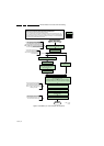
5.6 The Blinking LED Procedure
5.6.1 Introduction
The blinking LED procedure can be split up into two situations:
• Blinking LED procedure LAYER 1 error. In this case the
error is automatically blinked when the TV is put in CSM.
This will be only one digit error, namely the one that is
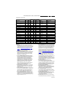
referring to the defective board (see table “5-2 Error code
overview”) which causes the failure of the TV. This
approach will especially be used for home repair and call
centres. The aim here is to have service diagnosis from a
distance.
• Blinking LED procedure LAYER 2 error. Via this procedure,
the contents of the error buffer can be made visible via the
front LED. In this case the error contains 2 digits (see table
“5-2 Error code overview
”) and will be displayed when SDM
(hardware pins) is activated. This is especially useful for
fault finding and gives more details regarding the failure of
the defective board.
Important remark:
For all errors detected by MIPS which are fatal => rebooting of
the TV set (reboot starts after LAYER 1 error blinking), one
should short the solder paths at start-up from the power OFF
state by mains interruption and not via the power button to
trigger the SDM via the hardware pins.
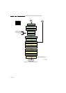
When one of the blinking LED procedures is activated, the front
LED will show (blink) the contents of the error buffer. Error
codes greater then 10 are shown as follows:
1. “n” long blinks (where “n” = 1 to 9) indicating decimal digit
2. A pause of 1.5 s
3. “n” short blinks (where “n”= 1 to 9)
4. A pause of approximately 3 s,
5. When all the error codes are displayed, the sequence
finishes with a LED blink of 3 s
6. The sequence starts again.
Example: Error 12 8 6 0 0.
After activation of the SDM, the front LED will show:
1. One long blink of 750 ms (which is an indication of the
decimal digit) followed by a pause of 1.5 s
2. Two short blinks of 250 ms followed by a pause of 3 s
3. Eight short blinks followed by a pause of 3 s
4. Six short blinks followed by a pause of 3 s
5. One long blink of 3 s to finish the sequence
6. The sequence starts again.
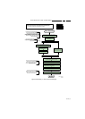
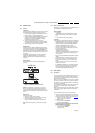
5.6.2 How to Activate
Use one of the following methods:
• Activate the CSM. The blinking front LED will show only
the latest layer 1 error, this works in “normal operation”
mode or automatically when the error/protection is
monitored by the standby processor.
In case no picture is shown and there is no LED blinking,
read the logging to detect whether “error devices” are
mentioned. (see section “5.8 Fault Finding and Repair
Tips, 5.8.6 Logging”).
• Activate the SDM. The blinking front LED will show the
entire content of the LAYER 2 error buffer, this works in
“normal operation” mode or when SDM (via hardware pins)
is activated when the tv set is in protection.
Important remark:
For all errors detected by MIPS which are fatal =>
rebooting of the TV set (reboot starts after LAYER 1 error
blinking), one should short the solder paths at start-up from
the power OFF state by mains interruption and not via the
power button to trigger the SDM via the hardware pins.
• Transmit the commands “MUTE” - “062500” - “OK”
with a normal RC. The complete error buffer is shown.
Take notice that it takes some seconds before the blinking
LED starts.
• Transmit the commands “MUTE” - “06250x” - “OK”
with a normal RC (where “x” is a number between 1
and 5). When x = 1 the last detected error is shown, x = 2
the second last error, etc.... Take notice that it takes some
seconds before the blinking LED starts.
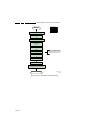
5.7 Protections
5.7.1 Software Protections
Most of the protections and errors use either the stand-by
microprocessor or the MIPS controller as detection device.
Since in these cases, checking of observers, polling of ADCs,
and filtering of input values are all heavily software based,
these protections are referred to as software protections.
There are several types of software related protections, solving
a variety of fault conditions:
• Protections related to supplies: check of the 12V, +5V,
+3V3 and 1V2.
• Protections related to breakdown of the safety check
mechanism. E.g. since the protection detections are done
by means of software, failing of the software will have to
initiate a protection mode since safety cannot be
guaranteed any more.
Remark on the Supply Errors
The detection of a supply dip or supply loss during the normal
playing of the set does not lead to a protection, but to a cold
reboot of the set. If the supply is still missing after the reboot,
the TV will go to protection.
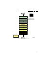
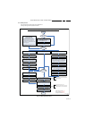
Protections during Start-up
During TV start-up, some voltages and IC observers are
actively monitored to be able to optimise the start-up speed,
and to assure good operation of all components. If these
monitors do not respond in a defined way, this indicates a
malfunction of the system and leads to a protection. As the
observers are only used during start-up, they are described in
the start-up flow in detail (see section “5.3 Stepwise Start-up
”).
5.7.2 Hardware Protections
The only real hardware protection in this chassis appears in
case of an audio problem e.g. DC voltage on the speakers. This
protection will only affect the Class D (7D10) and puts the
amplifier in a continuous burst mode (cyclus approximately 2
seconds).
Repair Tip
• There will be still picture available but no sound. While the
Class D amplifier tries to start-up again, the cone of the