


IC Data Sheets
EN 58 Q549.2E LA8.
2009-May-08
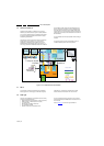
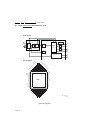
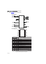
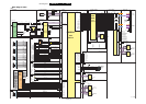
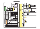
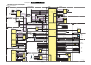
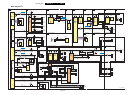
8.6 Diagram SSB: Audio B10A, TPA3123D (IC 7D10)
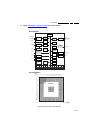
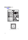
Figure 8-6 Internal block diagram and pin configuration
Block Diagram
Pin Configuration
18440_302_090303.eps
090303
1F
SD
PVCCL
PVCCR
VCLAMP
GAIN1
BYPASS
1F
1F
0.22 F
AGND
}
Control
Shutdown
Control
LIN
RIN
BSR
BSL
PGNDR
PGNDL
0.22 F
22 H
22 H
0.68 F
470 F
0.68 F
1F
470 F
GAIN0
AVCC
MUTE
ROUT
LOUT
1
2
3
4
5
6
7
8
9
10
11
12
24
23
22
21
20
19
18
17
16
15
14
13
PVCCL
SD
PVCCL
MUTE
LIN
RIN
BYPASS
AGND
AGND
PVCCR
VCLAMP
PVCCR
PGNDL
PGNDL
LOUT
BSL
AVCC
AVCC
GAIN0
GAIN1
BSR
ROUT
PGNDR
PGNDR
TERMINAL
I/O/P DESCRIPTION
24-PIN
NAME
(PWP)
Shutdown signal for IC (low = disabled, high = operational). TTL logic levels with compliance to
SD
2I
AVCC
RIN 6 I Audio input for right channel
LIN 5 I Audio input for left channel
GAIN0 18 I Gain select least-significant bit. TTL logic levels with compliance to AVCC
GAIN1 17 I Gain select most-significant bit. TTL logic levels with compliance to AVCC
Mute signal for quick disable/enable of outputs (high = outputs switch at 50% duty cycle, low =
MUTE 4 I
outputs enabled). TTL logic levels with compliance to AVCC
BSL 21 I/O Bootstrap I/O for left channel
PVCCL 1, 3 P Power supply for left-channel H-bridge, not internally connected to PVCCR or AVCC
LOUT 22 O Class-D 1/2-H-bridge positive output for left channel
PGNDL 23, 24 P Power ground for left-channel H-bridge
VCLAMP 11 P Internally generated voltage supply for bootstrap capacitors
BSR 16 I/O Bootstrap I/O for right channel
ROUT 15 O Class-D 1/2-H-bridge negative output for right channel
PGNDR 13, 14 P Power ground for right-channel H-bridge.
PVCCR 10, 12 P Power supply for right-channel H-bridge, not connected to PVCCL or AVCC
AGND 9 P Analog ground for digital/analog cells in core
AGND 8 P Analog ground for analog cells in core
Reference for preamplifier inputs. Nominally equal to AVCC/8. Also controls start-up time via
BYPASS 7 O
external capacitor sizing.
AVCC 19, 20 P High-voltage analog power supply. Not internally connected to PVCCR or PVCCL
Connect to ground. Thermal pad should be soldered down on all applications to properly
Thermal pad Die pad P
secure device to printed wiring board.