


Service Modes, Error Codes, and Fault Finding
EN 28 Q549.2E LA5.
2009-May-08
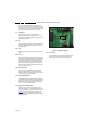
For all errors detected by MIPS which are fatal =>
rebooting of the TV set (reboot starts after LAYER 1
error blinking), one should short the solder paths
(SDM) at start-up from the power OFF state by mains
interruption and not via the power button to trigger the
SDM via the hardware pins.
• In CSM mode
– When entering CSM: error LAYER 1 will be displayed
by blinking LED. Only the latest error is shown.
• In SDM mode
– When SDM is entered via Remote Control code or the
hardware pins, LAYER 2 is displayed via blinking LED.
• In the ON state
– In “Display error mode”, set with the RC commands
“mute_06250X _OK” LAYER 2 errors are displayed via
blinking LED.
• Error display on screen.
– In CSM no error codes are displayed on screen.
– In SAM the complete error list is shown.
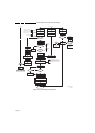
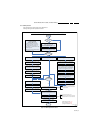
Basically there are three kinds of errors:
• Errors detected by the Stand-by software which lead to
protection. These errors will always lead to protection and
an automatic start of the blinking LED LAYER 1 error.
(see section “5.6 The Blinking LED Procedure
”).
• Errors detected by the Stand-by software which not
lead to protection. In this case the front LED should blink
the involved error. See also section “5.5 Error Codes
, 5.5.4
Error Buffer, Extra Info”. Note that it can take up several
minutes before the TV starts blinking the error (e.g. LAYER
1 error = 2, LAYER 2 error = 15 or 53).
• Errors detected by main software (MIPS). In this case
the error will be logged into the error buffer and can be read
out via ComPair, via blinking LED method LAYER 1-2
error, or in case picture is visible, via SAM.
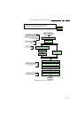
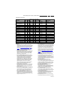
5.5.2 How to Read the Error Buffer
Use one of the following methods:
• On screen via the SAM (only when a picture is visible).
E.g.:
– 00 00 00 00 00: No errors detected
– 23 00 00 00 00: Error code 23 is the last and only
detected error.
– 37 23 00 00 00: Error code 23 was first detected and
error code 37 is the last detected error.
– Note that no protection errors can be logged in the
error buffer.
• Via the blinking LED procedure. See section 5.5.3 How to
Clear the Error Buffer.
•Via ComPair.
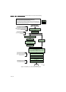
5.5.3 How to Clear the Error Buffer
Use one of the following methods:
• By activation of the “RESET ERROR BUFFER” command
in the SAM menu.
• With a normal RC, key in sequence “MUTE” followed by
“062599” and “OK”.
• If the content of the error buffer has not changed for 50+
hours, it resets automatically.
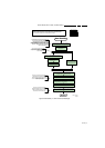
5.5.4 Error Buffer
In case of non-intermittent faults, clear the error buffer before
starting to repair (before clearing the buffer, write down the
content, as this history can give significant information). This to
ensure that old error codes are no longer present.
If possible, check the entire contents of the error buffer. In
some situations, an error code is only the result of another error
code and not the actual cause (e.g. a fault in the protection
detection circuitry can also lead to a protection).
There are several mechanisms of error detection:
• Via error bits in the status registers of ICs.
• Via polling on I/O pins going to the stand-by processor.
• Via sensing of analog values on the stand-by processor or
the PNX8543.
• Via a “not acknowledge” of an I
2
C communication.
Take notice that some errors need several minutes before they
start blinking or before they will be logged. So in case of
problems wait 2 minutes from start-up onwards, and then
check if the front LED is blinking or if an error is logged.