


25
En
01
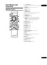
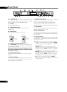
13 LCD (page 34)
Press to switch the liquid crystal display. When pressed
while the main unit display’s backlight is off, the backlight
turns on. (When pressed after the backlight has turned
on, switches the display.)
14 DISPLAY (page 35)
15 LOCK
Press to lock the remote control buttons. When pressed
again, the buttons are unlocked.
16 ENTER
Use this to execute the selected item, enter settings that
have been changed, etc.
17 SETUP indicator (page 37)
This lights when this unit is in the SETUP mode.
18 RETURN
Press to return to the previous screen.
19 SETUP (page 37)
Press to display the SETUP screen.
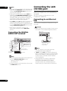
20 USB ports (MEMORY) (page 33)
USB storage devices can be connected here.
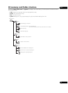
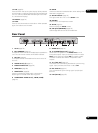
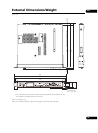
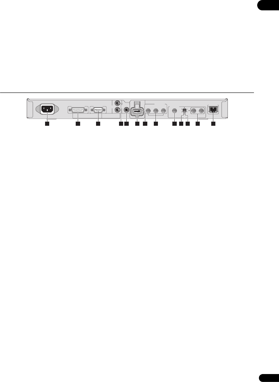
Rear Panel
1AC IN (page 33)
2 EXT TERMINAL (page 57)
An external switch can be connected here to operate this
unit. This can also be used as an RS-232C interface.
3 RS-232C (page 55)
A computer can be connected here for serial control of
this unit.
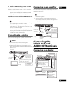
4 AUDIO OUT (L, R) (page 31)
5 DIGITAL AUDIO OUT (page 32)
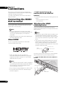
6 HDMI OUT (page 30)
7 HDMI holder (page 30)
Use this to fasten the HDMI cable in place when
attaching the included HDMI retaining cover.
8 COMPONENT VIDEO OUT (Y, CB/PB, CR/PR)
(page 31)
9VIDEO OUT (page 31)
10 TV SYSTEM (NTSC, PAL) (page 32)
Switches the TV system for the VIDEO OUT terminal
(composite output). Upon purchase, the switch is set to
NTSC (North American model)/PAL (European model).
This does not affect the HDMI or component video
outputs.
11 75 Ω (ON, OFF) (page 47)
This switch is for terminating the external synchronizing
signal. Upon purchase, the switch is set to ON.
12 EXT SYNC IN (page 47)
This is the external synchronizing signal input/output
terminal.
13 LAN (10/100) (page 32)
LAN(10/100)
EXT SYNC IN
ON
75
OFF
NTSC
C
R
/ P
R
C
B
/ P
B
Y
TV
SYSTEM
PAL
VIDEO OUT
COMPONENT
VIDEO OUT
HDMI
OUT
DIGITAL
AUDIO
OUT
AUDIO
OUT
RS-232CEXT TERMINAL
AC IN
L
R
1 2 3 9 12 135 64 10 118
7