09
58
En
• The newly assignable functions are as shown below.
3 Select the button to be newly assigned.
Use the /// buttons to select, then press the
ENTER button.
• The display in the Current column changes to the
newly assigned function.
• It is also possible to set multiple switches to the same
function.
• Press the RETURN button to return to the SETUP
screen.
• Press the SETUP button to close the Extend
Terminal screen.
To disable this unit’s functions
Use the / buttons to select the function you want to
disable in the Current column, then press the CLEAR
button. The display switches to Nothing.
To restore to the settings upon
purchase
Use the / buttons to select Default Setting in the
Current column, then press the ENTER button.
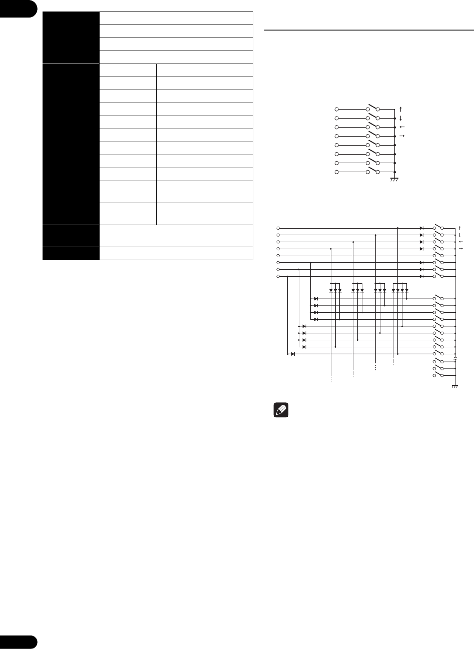
Connection to a controller
(switch interface)
The following shows an example of the connection
between a controller and this unit.
When not using a diode matrix
Fewer switches can be assigned (fewer functions can be
used).
When using a diode matrix (partial)
Up to 56 switches can be assigned.
Note
• Specifications of switch used in this example
– Contact resistance: 1 Ω or less
– Insulation resistance: 1 MΩ or more
–Non-lock type
• Specifications of diode used in this example
– Forward voltage (VF): 0.7 V or less (IF 1 mA)
– Surge current: 100 mA or less
– Forward current: 10 mA or less (VR = 10 V)
• Serial command control is required for synchronized
playback of this unit by frame precision.
Synchronized playback by frame precision is not
possible with parallel control or control by remote
control.
Cursor
(four keys)
Operations
(22 keys)
ENTER RECALL
PLAY SETUP
PAUSE MEMORY
STOP REPEAT
STEP FWD FRM/TIME
STEP REV CLEAR
RETURN DISPLAY
SCAN FWD PLAY MODE
SCAN REV NAVIGATOR
NEXT RES. +
(OUTPUT RESOLUTION +)
PREV RES. –
(OUTPUT RESOLUTION –)
Numbers
(10 keys)
0 – 9
List (20 keys) LIST1 – 20
SW1
SW2
SW3
SW4
SW5
ENTE
SW6 LIST 1
SW7 LIST
2
SW8 LIST
3
SW1
SW2
SW3
SW4
SW5
ENTE
SW6 LIST 1
SW7 LIST
2
SW8 LIST 3
1
2
3
4
5
6
7
8
9
