


INTERRUPT STRUCTURE S3F80P5_UM_ REV1.00
INTERRUPT TYPES
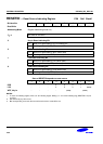
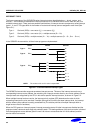
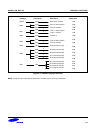
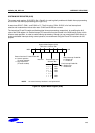
The three components of the S3C8/S3F8-series interrupt structure described above — levels, vectors, and
sources — are combined to determine the interrupt structure of an individual device and to make full use of its
available interrupt logic. There are three possible combinations of interrupt structure components, called interrupt
types 1, 2, and 3. The types differ in the number of vectors and interrupt sources assigned to each level (See
Figure 5-1):
Type 1: One level (IRQn) + one vector (V
1
) + one source (S
1
)
Type 2: One level (IRQn) + one vector (V
1
) + multiple sources (S
1
– S
n
)
Type 3: One level (IRQn) + multiple vectors (V
1
− V
n
) + multiple sources (S
1
− S
n
, S
n+1
− S
n+m
)
In the S3F80P5 microcontroller, all three interrupt types are implemented.
Vectors SourcesLevels
S
1
V
1
S
2
Type 2:
IRQn
S
3
S
n
V
1
S
1
V
2
S
2
Type 3:
IRQn
V
3
S
3
V
1
S
1
Type 1:
IRQn
V
n
S
n +
1
S
n
S
n +
2
S
n +
m
NOTE:
The number of S
n
and V
n
value is expandable.
Figure 5-1. S3C8/S3F8-Series Interrupt Types
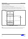
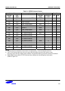
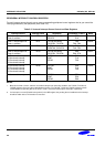
The S3F80P5 microcontroller supports seventeen interrupt sources. Thirteen of the interrupt sources have a
corresponding interrupt vector address; the remaining four interrupt sources share by one vector address. Seven
interrupt levels are recognized by the CPU in this device-specific interrupt structure, as shown in Figure 5-2.
When multiple interrupt levels are active, the interrupt priority register (IPR) determines the order in which
contending interrupts are to be serviced. If multiple interrupts occur within the same interrupt level, the interrupt
with the lowest vector address is usually processed first (The relative priorities of multiple interrupts within a
single level are fixed in hardware).
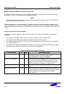
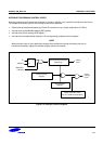
When the CPU grants an interrupt request, interrupt processing starts: All other interrupts are disabled and the
program counter value and status flags are pushed to stack. The starting address of the service routine is fetched
from the appropriate vector address (plus the next 8-bit value to concatenate the full 16-bit address) and the
service routine is executed.
5-2