


RESET S3F80P5_UM_ REV1.00
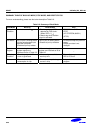
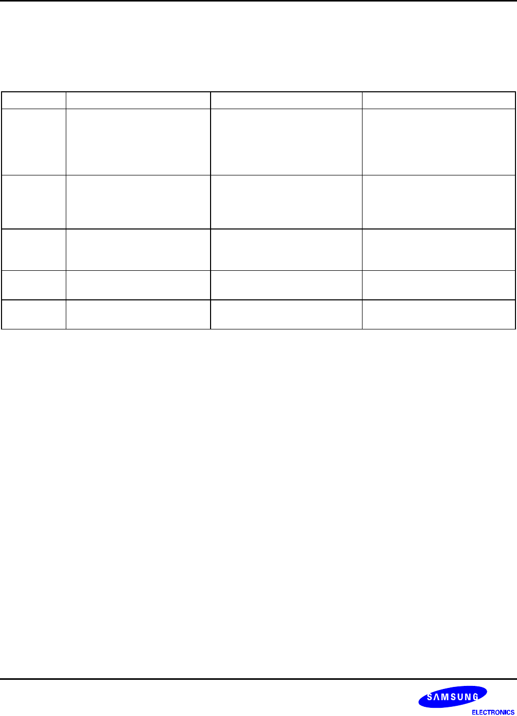
SUMMARY TABLE OF BACK-UP MODE, STOP MODE, AND RESET STATUS
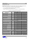
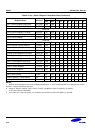
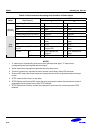
For more understanding, please see the below description Table 8-6.
Table 8-6. Summary of Each Mode
Item/Mode Back-up Reset Status Stop
Approach
Condition
• VDD is lower than V
LVD
• The rising edge at VDD is
detected by LVD circuit.
(When VDD ≥ V
LVD
)
• Watch-dog timer overflow
signal is activated.
• STOPCON ← # A5H
STOP
( LD STOPCON,#0A5H )
( STOP)
Port status • All I/O port is floating status
• All the ports become input
mode but is blocked.
• Disable all pull-up resister
• All I/O port is floating status
• Disable all pull-up resisters
• All the ports keep the previous
status.
• Output port data is not
changed.
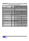
Control
Register
• All control register and
system register are
initialized as list of Table 8-2.
• All control register and system
register are initialized as list of
Table 8-2.
–
Releasing
Condition
• The rising edge of LVD
circuit is generated.
• After passing an oscillation
warm-up time
• External interrupt or reset
• SED & R Circuit.
Others • There is no current
consumption in chip.
• There can be input leakage
current in chip.
• It depends on control
program
8-20