


I/O PORTS S3F80P5_UM_ REV1.00
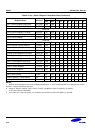
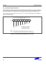
PULL-UP RESISTOR ENABLE REGISTERS
You can assign pull-up resistors to the pin circuits of individual pins in port0 and port1. To do this, you make the
appropriate settings to the corresponding pull-up resistor enable registers; P0PUR. These registers are located in
set 1, bank 0 at locations E7H, respectively, and are read/write accessible using Register addressing mode.
You can assign a pull-up resistor to the port 3 pins, P3.0 − P3.1 in the input mode using basic port configuration
setting in the P3CON registers.
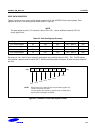
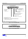
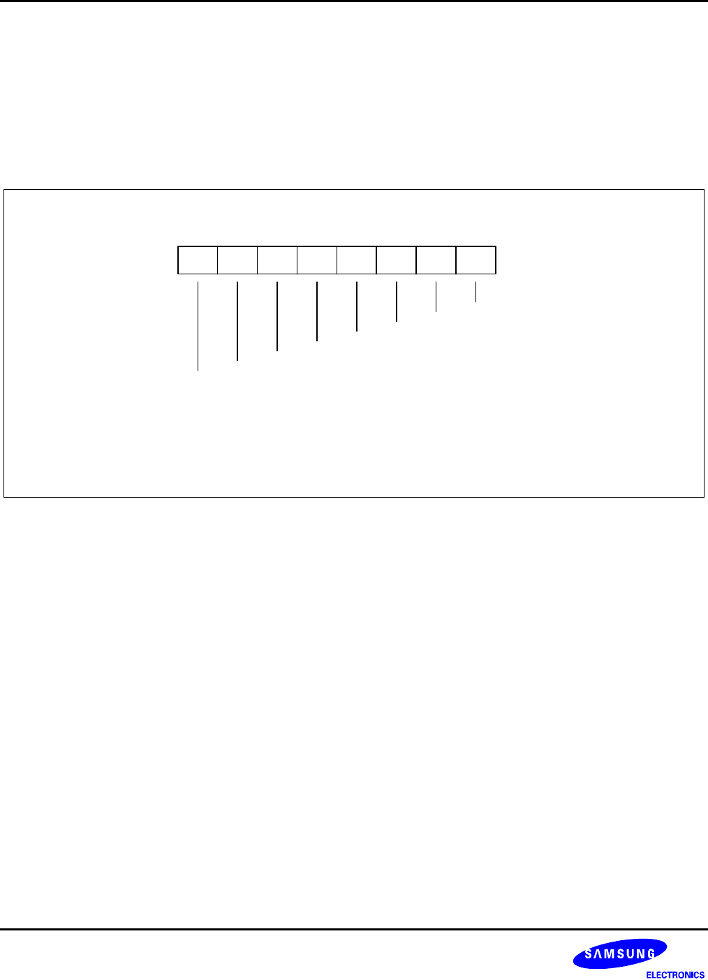
Pn.4
Pn.3
Set 1 , E7H, Bank0 , R/W
Pull-up Register Enable Registers (PnPUR, where n = 0)
.7 .6 .5 .4 .3 .2 .1 .0MSB LSB
Pn.1
Pn.2
Pn.5
Pn.6
Pn.7
Pn.0
NOTE:
Pull-up resistors can be assigned to the port 3 pins, P3.0
-
P3.1
by making the appropriate setting the port 3 control register P3CON.
Pull-up Resistor Enable Bit:
0 = Disable pull-up resistor
1 = Enable pull-up resistor
Figure 9-2. Pull-up Resistor Enable Registers (Port 0 and Port2)
9-4