


DEVELOPMENT TOOLS S3F80P5_UM_ REV1.00
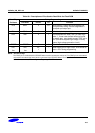
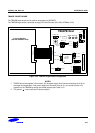
Table 19-1. Setting of the Jumper in TB80PB
JP# Description 1-2 Connection 2-3 Connection Default
Setting
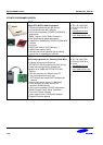
S1 Target board power source Use JP7(VCC) NOT connected Join 1-2
JP1 Target board mode selection H: Main-Mode L: EVA-Mode Join 2-3
JP2 Operation Mode H: User Mode L: Test-Mode Join 1-2
JP3 MDS version SMDS2 SMDS2+,SK-1200,OPENIce I-500 Join 2-3
JP4
To
User_Vcc
Target system is supplied V
DD
Target system is supplied
V
DD
from user system.
Target system is not supplied V
DD
from user system.
ON setting
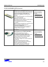
JP5 Board peripheral power
connection
Board peripheral power connection Connect
JP6 When supplied 5V in target board,
generation of 3.3V using
regulator.
In case of selection 3.3V of
Emulator (Not use 3.3V
regulator)
In case of selection 5V of
Emulator (Use 3.3V
Regulator)
Join 2-3
JP7,JP9 POWER connector JP7: VCC JP9:GND -
JP8
80PBX V
DD
power connection 80PB V
DD
power connection
Connect
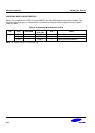
JP10 Clock source selection When using the internal clock source which is generated from
Emulator, join connector 2-3 and 4-5 pin. If user wants to use
the external clock source like a crystal, user should change the
jumper setting from 1-2 to 5-6 and connect Y1 to an external
clock source.
Emulator
2-3
4-5
JP11,12 NOT used for TB80PB - NOT
connected
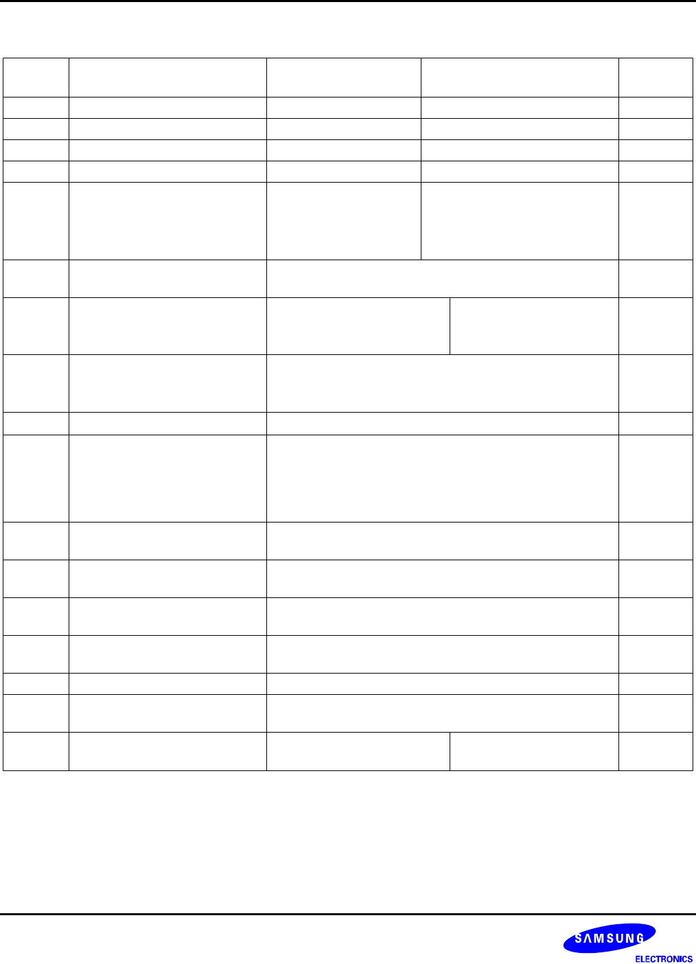
SW1 Generation low active reset signal
to S3F80PB EVA-chip
Push switch -
SW2 Smart option at address 3EH Dip switch for smart option. This 1byte is mapped address
3EH for special function. Refer to the page 2-3.
SW3 Smart option at address 3FH Dip switch for smart option. This 1byte is mapped address
3FH for special function. Refer to the page 2-3.
Y1 External clock source Connecting points for external clock source
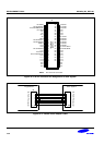
J3 Header for flash serial
programming signals
To program an internal flash, connect the signals with flash
writer tool.
J3
To
User_Vcc
Target System is supplied V
DD
Target Board is not supplied
V
DD
from user System.
Target Board is supplied V
DD
from user System.
Join 2-3
– nRESET LED
This LED is OFF when the Reset switch is ON.
– IDLE LED
This is LED is ON when the evaluation chip (S3E80PB) is in idle mode.
19-4